Visible light and infrared camera dynamic pose calculation method based on bidirectional homography matrix

A homography matrix, infrared camera technology, applied in the field of image processing and computer vision, can solve the problem of changing the position relationship between infrared camera and visible light camera

Active Publication Date: 2020-04-03
DALIAN UNIV OF TECH
View PDF3 Cites 4 Cited by
  • Summary
  • Abstract
  • Description
  • Claims
  • Application Information

AI Technical Summary

Problems solved by technology

[0006] The present invention aims to solve the change of the positional relationship between the infrared camera and the visible light camera due to factors such as temperature, humidity, vibration, etc.

Method used


Image

  • Visible light and infrared camera dynamic pose calculation method based on bidirectional homography matrix
  • Visible light and infrared camera dynamic pose calculation method based on bidirectional homography matrix
  • Visible light and infrared camera dynamic pose calculation method based on bidirectional homography matrix

Examples


Embodiment Construction

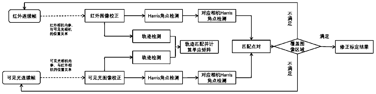
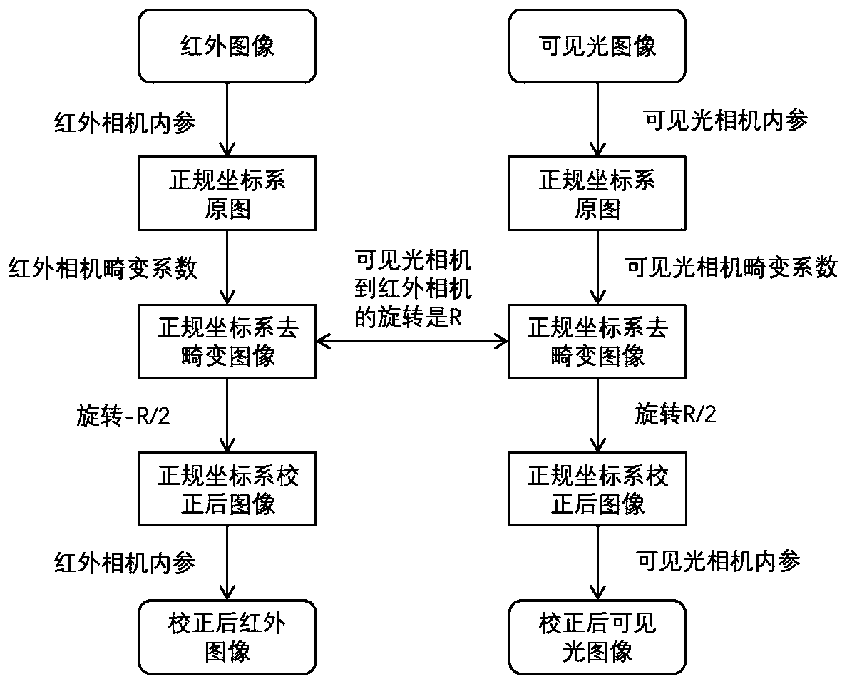
[0105] 1) Original image correction: The original image is de-distorted and binocularly corrected according to the internal parameters of the infrared camera and the visible light camera and the original external parameters. Process such as figure 2 shown.

[0106] 1-1) Calculate the coordinates in the normal coordinate system corresponding to the pixel points of the image. Among them, the normal coordinate system is the projection of the camera coordinate system on the plane Z=1; the camera coordinate system uses the center of the camera as the origin of the image coordinate system, the direction of the picture is the XY axis direction, and the direction perpendicular to the image is the Z axis direction Coordinate System. The pixel coordinate system takes the upper left corner of the picture as the origin, and its x-axis and y-axis are parallel to the x-axis and y-axis of the image coordinate system respectively. The unit of the pixel coordinate system is a pixel. The re...


PUM


Abstract

The invention belongs to the field of image processing and computer vision, and discloses a visible light and infrared camera dynamic pose calculation method based on a bidirectional homography matrix. The method comprises the steps that a transformation matrix between an infrared image and a visible light image is calculated by extracting and matching linear features on the infrared image and thevisible light image; Harris angular points are determined on the infrared image, initial correspondence of the detected Harris angular points on the visible light image is calculated according to thetransformation matrix, and the Harris angular points are detected around the initial correspondence to serve as final correspondence; and the same operation is performed on the visible light image. The matching number and matching efficiency of the infrared feature points and the visible light feature points are improved, so that the infrared camera and the visible light camera are subjected to joint self-calibration more effectively.

Description

technical field [0001] The invention belongs to the field of image processing and computer vision, and relates to a dynamic pose calculation method for visible light and infrared cameras based on a bidirectional homography matrix. Background technique [0002] Infrared (Infrared) is an electromagnetic wave with a wavelength between microwaves and visible light, and the wavelength is longer than red light. Substances above absolute zero (-273.15°C) can produce infrared rays. Because of its ability to observe through fog and rain, infrared images are widely used in different fields such as military defense, resource exploration, weather forecast, environmental monitoring, medical diagnosis and treatment, and marine research. Infrared rays can be used to shoot scenes through mist and smoke, and infrared photography can also be performed at night. The advantage of infrared camera imaging is that it can also image in extreme scenes (low light, rain and snow, dense fog, etc.), b...

Claims


Application Information

Patent Timeline
Patent Type & Authority Applications(China)
IPC IPC(8): G06T7/73G06T7/33G06T7/80G06T5/00G06F17/16
CPCG06T7/73G06T7/33G06T7/80G06T5/006G06F17/16G06T2207/10004G06T2207/10048
Inventor 仲维李豪杰柳博谦王智慧刘日升罗钟铉樊鑫
Owner DALIAN UNIV OF TECH
Why Eureka
Try Eureka