
Antenna device

An antenna device and antenna technology, applied in the field of communication, can solve the problems that the antenna device cannot be matched, it is inconvenient to apply to different scenarios, etc., and achieve the effect of convenient replacement of the antenna device, enhanced flexibility and adaptability, and convenient replacement

Active Publication Date: 2020-04-03
HUAWEI TECH CO LTD
View PDF12 Cites 3 Cited by
  • Summary
  • Abstract
  • Description
  • Claims
  • Application Information

AI Technical Summary

Problems solved by technology

However, after the current antenna leaves the factory, because the frequency band corresponding to the antenna has been fixed, it can only adapt to a single scenario. When complex and diverse communication scenarios appear, the antenna device cannot be matched, which is not convenient for the needs of different scenarios.

Method used


Image

  • Antenna device
  • Antenna device
  • Antenna device

Examples


Embodiment Construction

[0036] Below, some terms used in this application are explained:

[0037]1) A network device is a device in a wireless network, for example, a radio access network (radio access network, RAN) node that connects a terminal to the wireless network. Currently, examples of some RAN nodes are: base station, transmission reception point (transmission reception point, TRP), evolved Node B (evolved Node B, eNB), radio network controller (radio network controller, RNC), node B (Node B) B, NB), base station controller (base station controller, BSC), base transceiver station (base transceiver station, BTS), home base station (for example, homeevolved NodeB, or home Node B, HNB), base band unit (base band unit, BBU ), or a wireless fidelity (wireless fidelity, Wifi) access point (access point, AP), etc. In a network structure, the network device may include a centralized unit (centralized unit, CU) node, or a distributed unit (distributed unit, DU) node, or a RAN device including a CU no...


PUM


Abstract

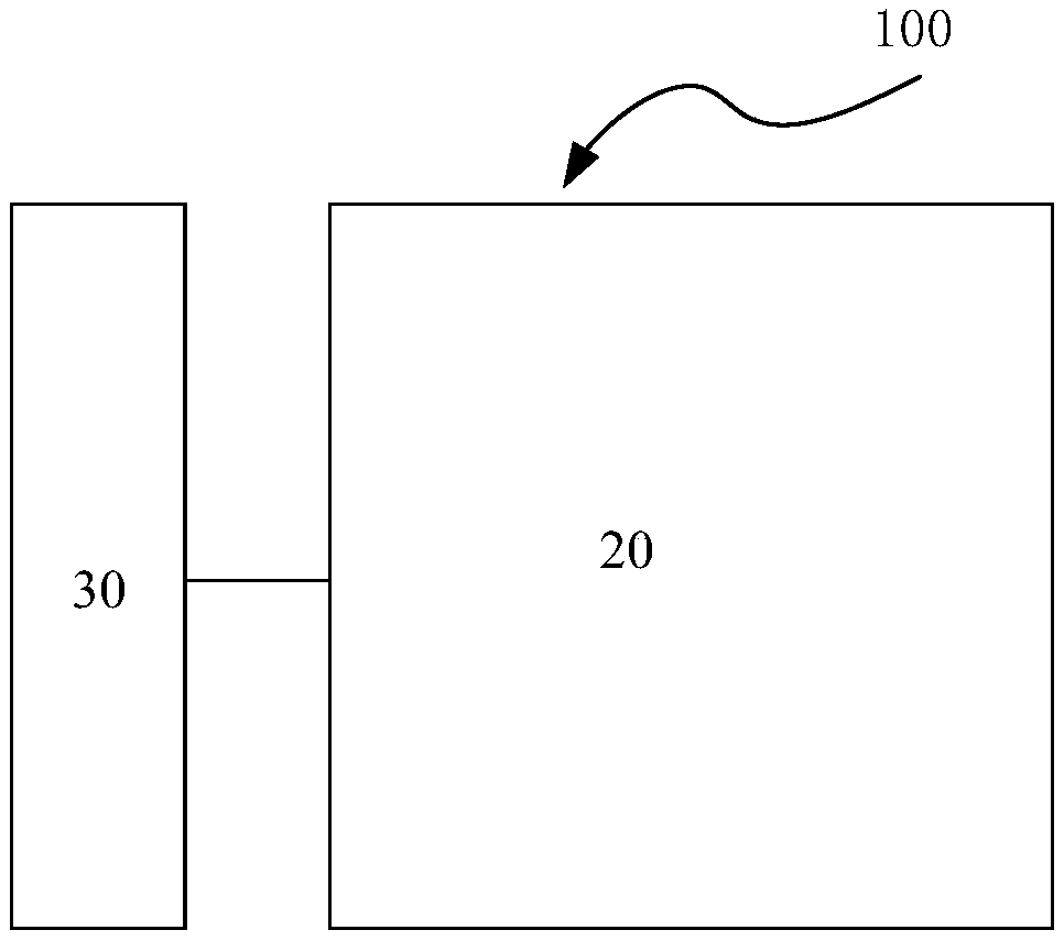
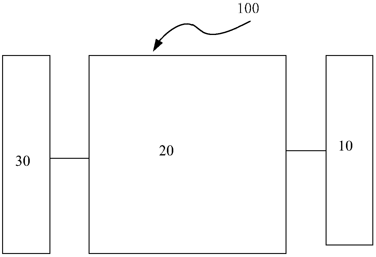
The invention provides an antenna device, which comprises a signal processing module and an antenna, and is characterized in that the signal processing module is at least used for feeding signals received or sent by the antenna, and the antenna is used for sending or receiving the signals. The signal processing module is pluggable and is connected with the antenna and the radio frequency unit ina pluggable mode. The signal processing module at least comprises a feed network, and by adopting the antenna device provided by the invention, devices for signal processing are integrated into the pluggable module, so that the signal processing module adapted to the scene can be flexibly replaced by the antenna device according to the requirements of the actual scene.

Description

technical field [0001] The present application relates to the technical field of communications, and in particular to an antenna device. Background technique [0002] The development of communication is changing with each passing day, and the communication system is updated very quickly. It is difficult for a single base station antenna form to meet the evolution requirements. In addition, the refined development of communication requires more and more detailed requirements for the shape of the antenna in order to match various complex and diverse communication scenarios. However, after the current antenna leaves the factory, since the frequency band corresponding to the antenna has been fixed, it can only adapt to a single scenario. When complex and diverse communication scenarios appear, the antenna device cannot be matched, which is not convenient for the needs of different scenarios. Contents of the invention [0003] The present application provides an antenna device...

Claims


Application Information

Patent Timeline
Patent Type & Authority Applications(China)
IPC IPC(8): H01Q1/50H01Q21/00H01Q21/06H01Q23/00
CPCH01Q1/50H01Q21/0006H01Q21/061H01Q23/00H01Q3/26H01Q21/0025
Inventor 肖伟宏王琳琳杨朝辉柳涛陈蕾
Owner HUAWEI TECH CO LTD
Learn More