
Drilling machine support device structure and construction method thereof

A device structure and drilling rig technology, which is applied to portable drilling rigs, workbenches, manufacturing tools, etc., can solve the problems of non-vertical holes, inconvenient operation, hidden safety hazards, etc., to improve the quality of holes, facilitate construction, and improve construction accuracy. Effect

Pending Publication Date: 2020-04-07
广西建工第五建筑工程集团有限公司
View PDF0 Cites 1 Cited by
  • Summary
  • Abstract
  • Description
  • Claims
  • Application Information

AI Technical Summary

Problems solved by technology

[0003] 1. It is easy to dislocate up and down when drilling, and the hole is not vertical
[0004] 2. It is necessary to set up mobile scaffolding in advance, which is inconvenient to operate;
[0005] 3. There are certain safety hazards when working on scaffolding

Method used


Image

  • Drilling machine support device structure and construction method thereof
  • Drilling machine support device structure and construction method thereof
  • Drilling machine support device structure and construction method thereof

Examples


Embodiment 1

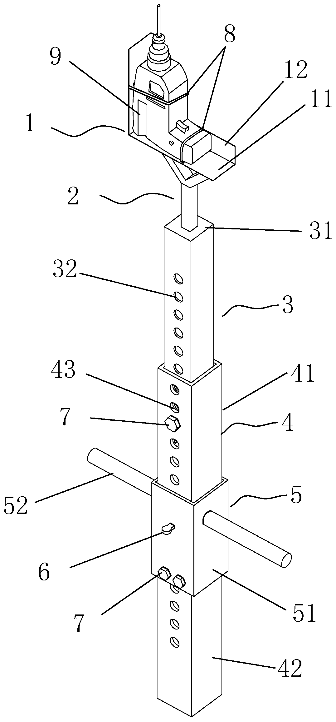
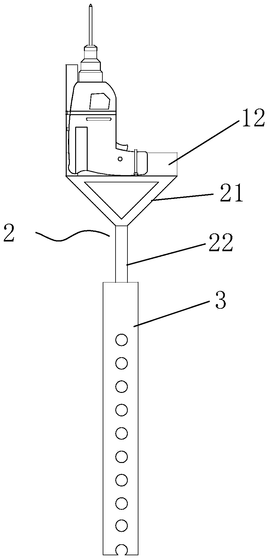
[0035] A kind of drilling rig support device structure, see figure 1 , including a fixed bracket and an adjustment device; the fixed bracket includes a fixed support 1 for installing a hand electric drill and a "Y" type fixed bracket 2; the fixed support includes a horizontally arranged L-shaped panel 11, and the L-shaped An L-shaped side of the panel is provided with an L-shaped side plate 12; the upper part 21 of the "Y"-shaped fixture is fixedly connected to the bottom of the L-shaped panel 11; the vertical plate and the L-shaped side of the L-shaped panel 11 The height of the vertical plate of the plate 12 does not exceed the installation position of the electric drill bit. The shape of the L-shaped panel 11 and the L-shaped side plate 12 is selected "L" type to facilitate the positioning of the electric drill and be fixed on the fixed support 1 to prevent the electric drill from shifting.

[0036] The adjustment device includes a coarse adjustment device and a fine adjus...

Embodiment 2

[0046] A construction method for a drilling rig support device structure, which is a construction method for a drilling rig support device structure described in Embodiment 1, and its construction process is as follows: A, determining the structural size of the drilling rig support device → B, making the drilling rig support device The components of the seat device structure → C, the structure of the assembled drilling rig support device → D, the rough adjustment of the structural height of the drilling rig support device → E, the fine adjustment of the structural height of the drilling rig support device → F, and precise drilling; specifically:

[0047] The step A, determining the structural size of the drilling rig support device includes the following main contents: determine the position of each positioning hole, and the diameter of the positioning hole is 10mm; select angle iron as the material of the fixed support 1; select square steel as " The material of Y " type fixed...


PUM


Abstract

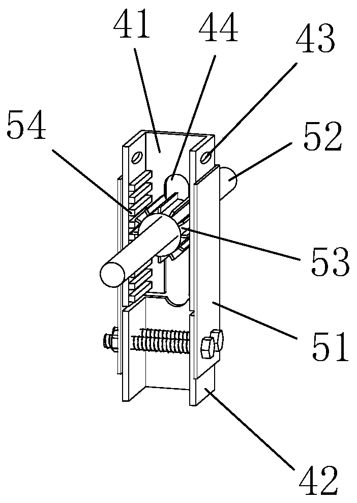
A drilling machine support device structure comprises a fixing bracket, a coarse adjustment device and a fine adjustment device. The fixing bracket comprises a fixing support used for installing an electric hand drill and a Y-shaped fixing frame. The coarse adjustment device comprises a first telescopic bracket and a second telescopic bracket. The fine adjustment device comprises a fine adjustmentbox, an adjustment handle, a gear and a rack. The bottom of the first telescopic support is sleeved with the upper half section of the second telescopic support. The fine adjustment box wraps the joint of the upper half section and the lower half section of the second telescopic support and is fixed to the lower half section of the second telescopic support through a bolt. The bottom end of the upper half section of the second telescopic support is provided with a long-strip-shaped lifting hole used for allowing the adjustment handle to penetrate through. The rack is installed in the side, perpendicular to the gear, of the inner wall of the upper half section of the second telescopic support, and the gear is fixedly installed in the middle of the adjustment handle and engaged with the rack. According to the invention, construction is convenient, high-place operation is not needed, the pore-forming quality is guaranteed, and steel bar deviation is avoided.

Description

technical field [0001] The invention relates to an auxiliary tool for planting reinforcement, in particular to a drilling rig support device structure and a construction method used in the construction of reinforcement. Background technique [0002] At present, the reinforcement of the roof of the secondary structure in the construction project is constructed by erecting scaffolding. The existing hand electric drill drilling construction technology brings a lot of inconvenience to the construction: [0003] 1. It is easy to misalign up and down when drilling, and the hole is not vertical. [0004] 2. It is necessary to set up mobile scaffolding in advance, which is inconvenient to operate; [0005] 3. There are certain potential safety hazards when working on scaffolding. Contents of the invention [0006] The purpose of the present invention is to provide a drilling rig support device structure, which is convenient for construction, does not need to set up and dismantl...

Claims


Application Information

Patent Timeline
Patent Type & Authority Applications(China)
IPC IPC(8): B23B45/14
CPCB25H1/0035
Inventor 宁绍栋郑晖陈善尧梁晓东陆尘
Owner 广西建工第五建筑工程集团有限公司
Learn More