Tire curing capsule and preparation method thereof

A technology for vulcanizing bladders and tires, which is applied to tires, other household appliances, household components, etc., can solve the problems of improvement, no bladder neck and edge, and no technical solution for tire curing bladder damage. The effect of stability, ensuring its own integrity, and strong ability to withstand deformation

Inactive Publication Date: 2020-04-07
YONGYI RUBBER CO LTD
7 Cites 0 Cited by

AI-Extracted Technical Summary

Problems solved by technology

[0004] Chinese patent CN101462329B discloses an inflatable bladder for forming a pneumatic tire to be installed in a tire curing machine, mainly improving the intermediate body of the tire curing bladder to more closely match the green tire geometry and prevent the tire from curing Deforma...

Method used

With butyl rubber and chlorinated butyl rubber as the main body of sizing material, the degree of unsaturation of butyl rubber is low, and the airtightness is excellent, and active point is few on its molecular chain simultaneously, and self-adhesiveness is poor; Chlorinated butyl rubber There are chlorine active points in it, which can improve the deficiency of butyl rubber; the combination of the two, together with an appropriate amount of ordinary carbon black, acetylene carbon black, aluminum oxide, zinc oxide masterbatch, stearic acid, paraffin, vulcanized resin, Sulfur, adopting the rubber mixing process in the present invention, the prepared film has high uniformity and enhanced flex resistance; the tire curing bladder prepared by further processing the above film is damaged when it is assembled with the tire vulcanizing machine during use. Failed tire curing bladders are greatly reduced.
[0038] The cross section of the first protrusion 13 and the second protrusion 14 is arc-shaped. The first protrusion 13 and the second protrusion 14 are arranged along the capsule neck 4, and there is a first groove 15 between them. When assembling with a tire vulcanizing machine, a ring will be placed inside the first groove 15. The sealing ring, and the tire vulcanizer will form a certain fastening force on the first protrusion 13 and the second protrusion 14 to achieve a good fixing and sealing effect. The arc-shaped first protrusion 13 and the second protrusion 14 have a strong ability to withstand deformation when stressed, and the absence of glue on the edge provides a space for deformation of the highest protrusion. The height of the second protrusion 14 ≥ the height of the first protrusion 13 . The height of the first protrusion 13 is 10%-50% of the thickness of the neck 4 of the capsule, and the height of the second protrusion 14 is 10%-80% of...

Abstract

The invention discloses a tire curing capsule and a preparation method thereof, and relates to the technical field of tire curing capsules. The capsule comprises a middle body, and capsule shoulder parts, capsule side parts, capsule neck parts and edge clamping parts which are sequentially and symmetrically distributed on the two sides of the middle body; the outer walls of the capsule neck partsprotrude outwards to form first protrusions and second protrusions, the concave positions between the first protrusions and the second protrusions are called as first grooves, and the concave positions between the second protrusions and the edge clamping parts are called as second grooves; the front ends of the edge clamping parts are provided with front shrinking ends, expanding parts are arranged in the circumferential direction, and conical parts are arranged at the joints where the edge clamping parts and the second grooves are connected. Compared with the prior art, the beneficial effectsare that the capsule neck parts and the edge clamping parts at the assembly part of the tire curing capsule and a tire vulcanizing machine are improved, so that the assembly stability and sealing performance of the tire curing capsule and the tire vulcanizing machine can be improved; and in combination with a preparation method of the tire curing capsule, the failure rate caused by damage to thetire curing capsule at the assembly position of the tire curing capsule and the tire vulcanizing machine during use is reduced.

Application Domain

TyresDomestic articles

Technology Topic

Composite materialEngineering +2

Image

  • Tire curing capsule and preparation method thereof
  • Tire curing capsule and preparation method thereof

Examples

  • Experimental program(1)

Example Embodiment

[0032] The specific implementation of the present invention will be described below with reference to the drawings and embodiments:
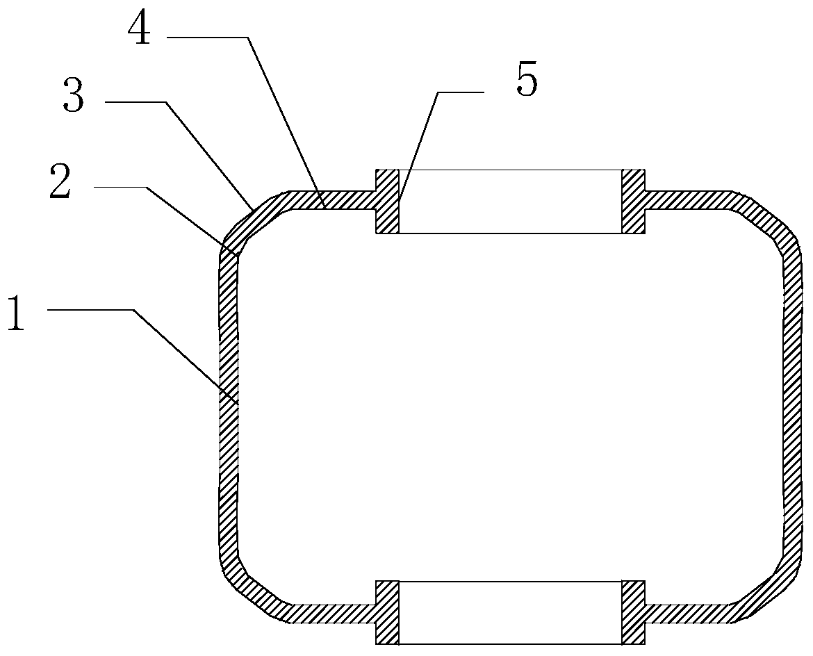
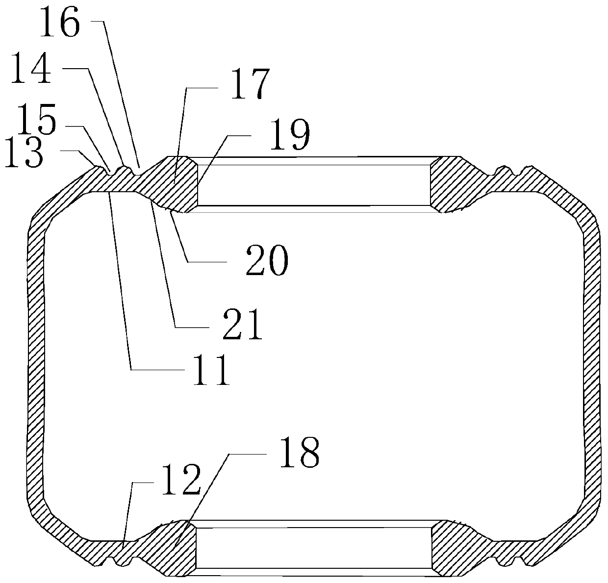
[0033] It should be noted that the structure, ratio, size, etc. illustrated in the drawings attached to this specification are only used to match the content disclosed in the specification for the understanding and reading of those familiar with this technology, and are not intended to limit the implementation of the present invention. The limitation conditions, any structural modification, proportional relationship, change or size adjustment, shall fall within the scope of the technical content disclosed in the present invention without affecting the effects and objectives that can be achieved by the present invention In the range.
[0034] At the same time, the terms such as "upper", "lower", "left", "right", "middle" and "one" cited in this specification are only for the convenience of description and are not used to limit the text. The scope of implementation of the invention, the change or adjustment of the relative relationship, shall be regarded as the scope of implementation of the invention without substantial changes to the technical content.
[0035] Reference Figure 1-2 , A tire curing bladder, comprising a middle body 1, which plays a main expansion role, a bladder shoulder 2, a bladder side 3, a bladder neck 4, and a clamping edge 5 that are sequentially and symmetrically distributed on both sides of the middle body 1;
[0036] A first protrusion 13 protrudes outward on the outer wall of the capsule neck 4 near the capsule side 3, and a second protrusion 14 protrudes outward on the outer wall of the capsule neck 4 near the clamping edge 5, The depression between the first protrusion 13 and the second protrusion 14 is called the first groove 15, and the depression between the second protrusion 14 and the clamping edge portion 5 is called the second groove 16; the first protrusion 13 , The second protrusion 14, the first groove 15 and the second groove 16 are annular along the capsule neck 4; the capsule neck 4 includes an upper neck 11 and a lower neck 12, as described above The neck 11 is carried out, and the two structures are symmetrical.
[0037] The end of the clamping edge portion 5 close to the center line of the intermediate body 1 forms a tapered forward retracted end 19 that gradually contracts from a position far from the center line of the intermediate body 1 to a position close to the center line of the intermediate body 1; the clamping edge portion 5 The outer side perpendicular to the center line of the intermediate body 1 protrudes outward to form a tapered expansion portion 20 that gradually shrinks from the inside to the outside; the second groove 16 and the clamping edge 5 are formed at the junction of the second The groove 16 is a tapered cone 21 that gradually expands toward the clamping edge 5; the clamping edge 5 includes an upper clamping edge 17 and a lower clamping edge 18. The description is performed on the clamping edge 17 above, and the structure of the two is symmetrical.
[0038] The cross sections of the first protrusion 13 and the second protrusion 14 are arc-shaped. The first protrusion 13 and the second protrusion 14 are arranged along the neck 4 of the capsule, and there is a first groove 15 between them. When assembling with the tire vulcanizer, a ring shape is placed inside the first groove 15 Sealing ring, and the tire vulcanizing machine will form a certain fastening force on the first protrusion 13 and the second protrusion 14 to achieve a good fixing and sealing effect. The arc-shaped first protrusion 13 and the second protrusion 14 have a strong ability to withstand deformation when subjected to a force, and no glue at the edge provides a space for deformation at the highest protrusion. The height of the second protrusion 14 ≥ the height of the first protrusion 13. The height of the first protrusion 13 is 10%-50% of the thickness of the capsule neck 4, and the height of the second protrusion 14 is 10%-80% of the thickness of the capsule neck 4.
[0039] The width of the retracted end 19 is 10%-50% of the width of the clamping edge 5.
[0040] A method for preparing tire curing bladder, preparing the above tire curing bladder; in the raw materials of the tire curing bladder, 60-80 parts of butyl rubber, 20-40 parts of chlorinated butyl rubber, 20-30 parts of ordinary carbon black, and acetylene 20-30 parts of carbon black, 5-10 parts of aluminum oxide, 3-5 parts of zinc oxide masterbatch, 1-2 parts of stearic acid, 1-3 parts of paraffin wax, 2-4 parts of vulcanized resin, sulfur 1- 3 copies;
[0041] Proceed as follows:
[0042] S1. Weigh the materials according to the formula, in parts by weight,
[0043] S2, the film is processed by mixing rubber:
[0044] S21. One-stage rubber mixing: butyl rubber, chlorinated butyl rubber, 1/2 ordinary carbon black, 1/2 acetylene carbon black, 1/2 aluminum oxide, zinc oxide masterbatch, hard fat Add acid and paraffin wax into the internal mixer, the internal mixing temperature is 80-110℃, the time is 1-10min, and the internal mixing compound is discharged;
[0045] S22, two-stage rubber mixing: add the banbury compound in S21 to the open mill, while adding the remaining 1/2 ordinary carbon black, 1/2 acetylene carbon black, and 1/2 aluminum oxide. Mix for 5-10min at 100-120℃; then add vulcanized resin and sulfur, then mix for 2-5min, then discharge the mixed rubber;
[0046] S23. Three-stage rubber mixing: heat the barrel temperature of the rubber extruder to 50-55°C, the die head temperature to 60-65°C, and the extruder mouth temperature to 70-75°C for heat preservation. The mixed rubber material is put into the feed port of the extruder, the extruder screw is started, and the extrusion pressure is controlled at 10-12MPa. The extruder screw extrudes the capsule rubber from the barrel to the head, and finally extrudes the sheet rubber from the extrusion port The output speed of flake rubber is controlled at 2.5-3m/min;
[0047] S24. Hang the sheet-shaped rubber material on the rack and cool it to room temperature naturally;
[0048] S3. Injection vulcanization: Put the film obtained in S24 into an injection vulcanizing machine, the temperature of the screw is controlled at 70-90℃, the pressure is controlled at 16-18MPa; the injection curing temperature is 180-200℃, and the curing time is 30-42min; After the end, the injection vulcanizer pushes the tire bladder out of the mold cavity to prepare a high-strength tire vulcanizing bladder.
[0049] Among them, the specific preparation steps of the zinc oxide masterbatch are as follows: first put the carrier rubber and zinc stearate into an open mill according to the proportions, and masticate uniformly; then put the above products, zinc oxide powder and naphthenic mineral oil in proportions Internal mixer, mixing and banburying; finally, the materials obtained from mixing and banburying are thrown into the transportation hopper, transported to the conical twin-screw forced kneader, after kneading, transported to the single-screw cold feed extruder, granulated and discharged .
[0050] Furthermore, the degree of unsaturation of butyl rubber is 0.5-2%, and the chlorinated butyl rubber contains 1.5-2.5% chlorine.
[0051] In the tire curing bladder assembled with the tire vulcanizer, the causes of damage are mechanical damage, flexural damage, and premature aging damage due to poor sealing, etc., which are related to unstable assembly, poor sealing, and material. In the present invention, the structure of the capsule neck 4 and the clamping edge portion 5 is improved in design. The design expansion portion 20 thickens the clamping edge portion 5 as a whole to increase its contact area with the tire vulcanizer assembly and improve the stability of the fit. The front end of the clamping edge 5 is designed with a tapered forward contraction end 19, which provides space for the clamping edge 5 to deform when the tire vulcanizer is compressed. The cone 21 enhances the connection between the clamping edge 5 and the capsule neck 4. When the tire is vulcanized, when the bladder neck 4 is in contact with the tire vulcanizer, the first groove 15 and the second groove 16 are cavities, and the annular sealing ring is assembled in the first groove 15 and the second groove during installation. The position of the two grooves 16 can play a sealing role; when the mold is clamped and compressed, the arc-shaped first protrusion 13 and the second protrusion 14 have strong ability to withstand deformation when subjected to force, and the edge without glue provides the highest The deformed space at the protrusion ensures the integrity of the tire curing bladder. In addition, the above design increases the size of the bladder neck 4 and the clamping edge 5, improves the strength of the tire curing bladder in the bladder neck 4 and the clamping edge 5, and also increases the distance between the tire curing bladder and the tire vulcanizer. The contact area.
[0052] With butyl rubber and chlorinated butyl rubber as the main rubber material, butyl rubber has low unsaturation and excellent air tightness. At the same time, its molecular chain has fewer active points and poor self-adhesiveness; chlorinated butyl rubber has Chlorine active points can improve the deficiencies of butyl rubber; the combination of the two, with an appropriate amount of ordinary carbon black, acetylene carbon black, aluminum oxide, zinc oxide masterbatch, stearic acid, paraffin wax, vulcanized resin, and sulfur. In the rubber mixing process of the present invention, the prepared film has high uniformity and enhanced flex resistance; the tire vulcanizing bladder prepared by using the above film is further processed, and the tire that fails due to damage at the assembly place of the tire vulcanizer during use Vulcanization bladder is greatly reduced.
[0053] In use, the tire curing bladder produced by the preparation method and the improved structure of the present invention, the proportion of the tire curing bladder that fails due to damage at the assembly place of the tire curing press during use is reduced to 3%.

PUM

no PUM

Description & Claims & Application Information

We can also present the details of the Description, Claims and Application information to help users get a comprehensive understanding of the technical details of the patent, such as background art, summary of invention, brief description of drawings, description of embodiments, and other original content. On the other hand, users can also determine the specific scope of protection of the technology through the list of claims; as well as understand the changes in the life cycle of the technology with the presentation of the patent timeline. Login to view more.

Similar technology patents

Heat-Exchange Apparatus

Owner:OBSHCHESTVO S OGRANICHENNOJ OTVETSTVENNOSTJU PRORYVNYE INNOVATSIONNYE TEKHNOLOGII

Nano calcium carbonate drying device

Owner:湖州互融新材料科技有限公司

Horizontal stirring apparatus

InactiveCN102836656Aincrease contact areastir quickly
Owner:扬州庆松化工设备有限公司

Classification and recommendation of technical efficacy words

Why Eureka
Try Eureka