


Quick Research
Generate reliable direction feasibility study reports for your R&D in just a few steps.

Technical Q&A
Discover and master advanced knowledge NOW. Basics, ideas, possibilities, all at once.

Find Solutions
As an expert in R&D theories, this can generate solutions to your technical problems instantly.

Evaluate Feasibility
Analyze your overall solution with one click, know your potential R&D risks in advance.

Monitor Landscape
Get weekly tech updates, stay abreast of the latest tech innovations and key insights.
Hydraulic suspension, vehicle hydraulic suspension system and control method thereof
A hydraulic mount and hydraulic technology, applied in the field of vehicle parts, can solve problems such as unadjustable, single, and limited hydraulic mount use effects, and achieve the effect of improving the use effect
- Summary
- Abstract
- Description
- Claims
- Application Information
AI Technical Summary
Problems solved by technology
Method used
Image

Examples
Embodiment 1
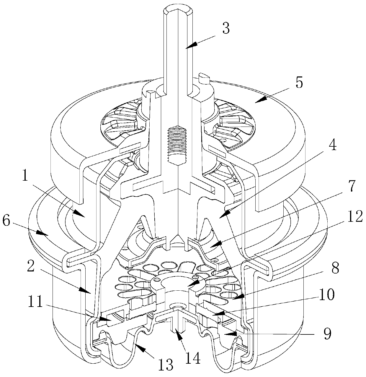
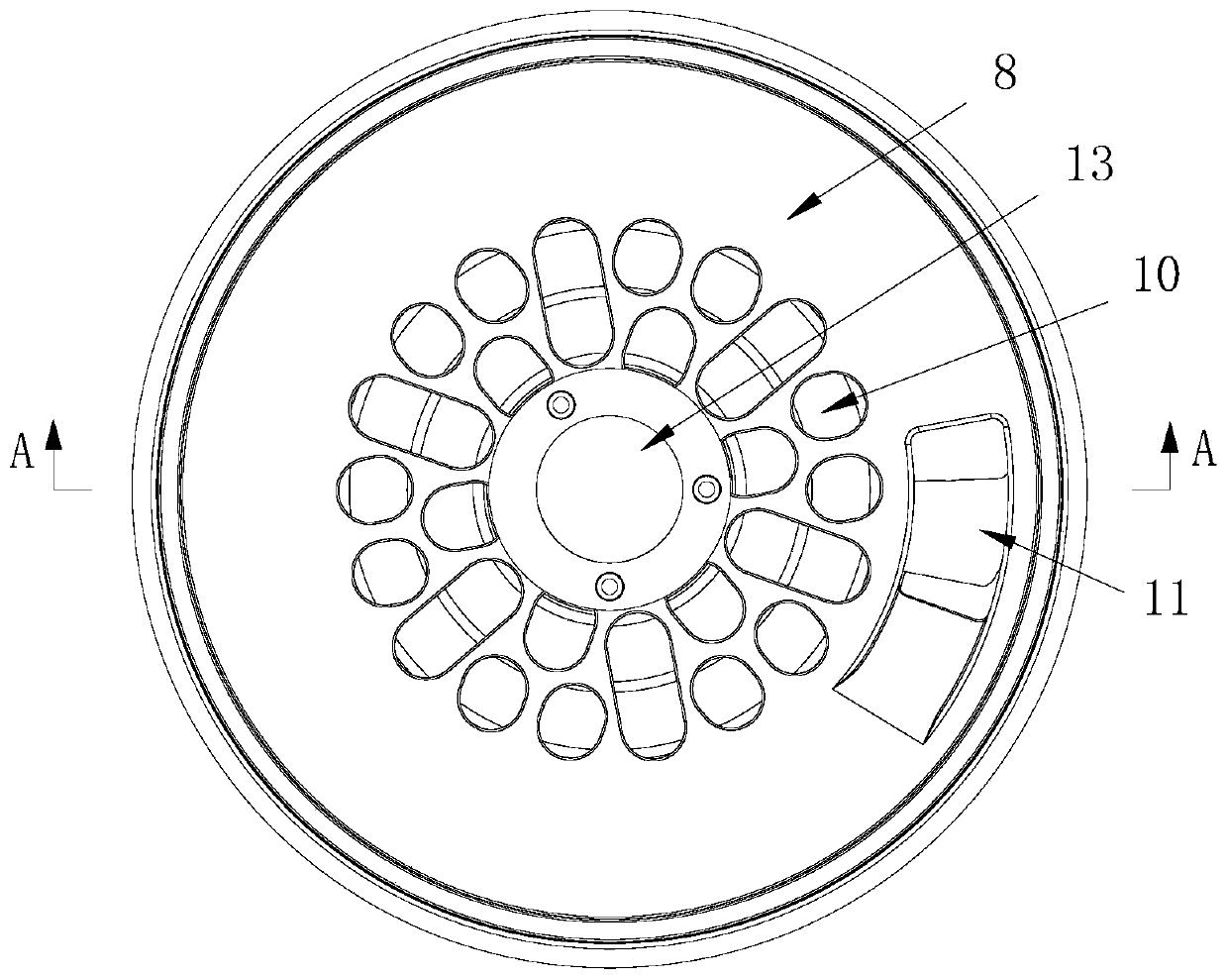
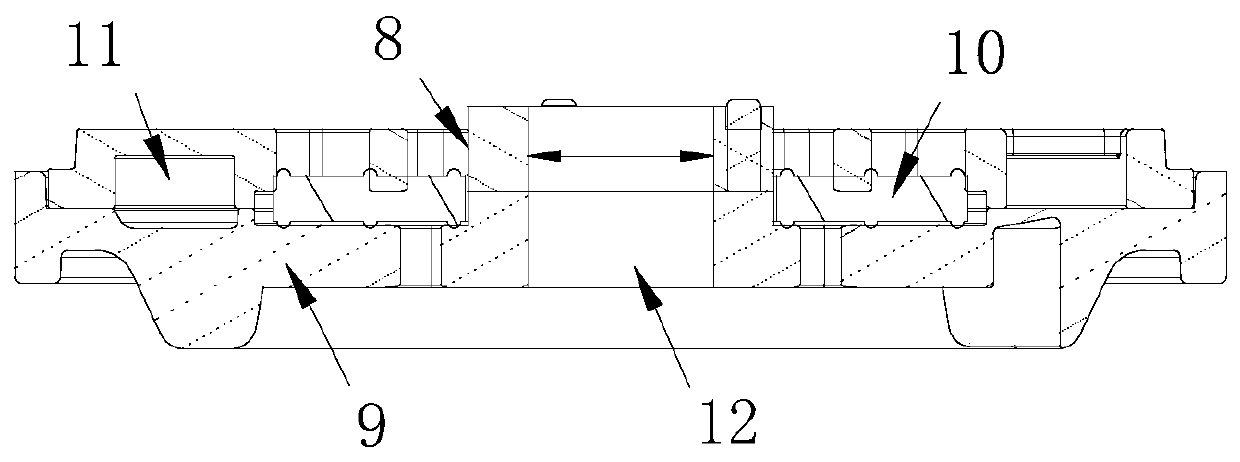
[0035] This embodiment relates to a hydraulic mount, such as figure 1 and combine Figure 2 to Figure 4 As shown in , its overall composition mainly includes a housing, a rubber main spring 3 , a connecting piece 3 , a leather cup 13 , a flow channel assembly and a control piece 14 .
[0036] Wherein, the shell is used as the structural basis of the entire hydraulic mount, not only for carrying other components, but also for forming the press fit of the hydraulic mount on the first external component. The first component is generally the body of the vehicle, and the second component connected to the connector 3 below corresponds to the powertrain mounted on the vehicle body. At the same time, as an exemplary structural form, the housing of this embodiment also includes an upper bracket 1 and a lower bracket 2 that are fastened up and down, and an end that is connected with the upper bracket 1 and the lower bracket 2 is formed with a valgus arrangement. The two flanges are cl...
Embodiment 2
[0051] This embodiment relates to a vehicle hydraulic mount system, such as Figure 6 As shown in , it includes a suspension unit 100 composed of the hydraulic mount in Embodiment 1, a drive unit 17 connected to the connection end of the control member 14 in the hydraulic mount, and a drive unit 17 for collecting the vibration excitation of the vehicle. The frequency acquisition unit 16, and the control unit 15 that receives the acquisition signal of the acquisition unit 16 to control the action of the drive unit 17 to output a linear driving force.
[0052] Wherein, when the control unit 15 controls the operation of the drive unit 17, the control member 14 receives the linear driving force and can reciprocate to open or block the second flow channel 12, so as to realize the adjustment of the performance of the hydraulic mount.
[0053] The acquisition unit 16 generally adopts an acceleration sensor installed on the vehicle, the control unit 15 can be integrated into the vehic...
PUM
| Property | Measurement | Unit |
|---|---|---|
| Thickness | aaaaa | aaaaa |
Abstract
Description
Claims
Application Information
 - R&D Engineer
- R&D Manager
- IP Professional
- Industry Leading Data Capabilities
- Powerful AI technology
- Patent DNA Extraction
Browse by: Latest US Patents, China's latest patents, Technical Efficacy Thesaurus, Application Domain, Technology Topic, Popular Technical Reports.
© 2024 PatSnap. All rights reserved.Legal|Privacy policy|Modern Slavery Act Transparency Statement|Sitemap|About US| Contact US: help@patsnap.com