Multi-curved glass forming method and forming device

A molding method and multi-curved surface technology, which is applied in the molding of multi-curved glass and the field of multi-curved glass forming devices, can solve the problems of dependence, large roughness of concave curved surface and convex curved surface of curved glass, and achieve mold roughness Small, improve surface quality, not easily deformed

Inactive Publication Date: 2020-04-07
SHENZHEN JINGJIANG YUNCHUANG TECH CO LTD
9 Cites 0 Cited by

AI-Extracted Technical Summary

Problems solved by technology

Curved glass needs to be in contact with the surface of the mold when it is formed, resulting in greater roughness of the concave and convex surfaces of the curved glass afte...

Method used

Adopt the molding method of multi-curved surface glass of the present invention, because of the material property of mold 200, molding area 30 can directly utilize its own through hole 207, adopt air pump 300 to vacuumize inside it to make mold 200 and glass substrate Gas between sheets 400 is vented. Because the gas is exhausted through the through hole 207 of the mold 200 itself, the exhaust is relatively uniform, so that the glass substrate 400 is not easily deformed during the bending process. The mold 200 can directly copy the outer surface design of the multi-curved glass 500 , and has a simple structure and high precision. The forming method of the multi-curved glass solves the problem that it is difficult to process and form complex-shaped glass containing multiple curve...

Abstract

The invention provides a multi-curved glass forming method. The multi-curved glass forming method comprises the following steps that a forming furnace comprises a conveying mechanism, an interaction area, a heating area, a forming area and a cooling area; a plurality of molds are placed in each functional area, are made of porous materials and are provided with grooves or bosses for profiling theouter surface of multi-curved glass; a glass substrate is fed to the molds in the interaction area through the interaction area; the heating area heats the glass substrate to reach a set temperature;the glass substrate is continuously heated in the forming area; an air exhauster communicates with the forming area to vacuumize the forming area, so that gas penetrates through through holes of the molds to enter the air exhauster; the cooling area cools the glass substrate to obtain multi-curved glass; and the multi-curved glass is taken out of the molds in the cooling area. Gas is exhausted from the through holes of the molds, exhaust is uniform, the through holes are tiny holes, no through hole trace is left when the glass substrate is formed, and thus the surface quality of multi-curved glass forming is improved.

Application Domain

Glass reforming apparatus

Technology Topic

Moulding deviceGlass forming +1

Image

  • Multi-curved glass forming method and forming device
  • Multi-curved glass forming method and forming device
  • Multi-curved glass forming method and forming device

Examples

  • Experimental program(1)

Example Embodiment

[0022] In order to be able to understand the above objectives, features and advantages of the present invention more clearly, the present invention will be described in detail below with reference to the accompanying drawings and specific embodiments. It should be noted that the embodiments of the application and the features in the embodiments can be combined with each other if there is no conflict.
[0023] In the following description, many specific details are explained in order to fully understand the present invention. The described embodiments are only a part of the embodiments of the present invention, rather than all of them. Based on the embodiments of the present invention, all other embodiments obtained by a person of ordinary skill in the art without creative work shall fall within the protection scope of the present invention.
[0024] Unless otherwise defined, all technical and scientific terms used herein have the same meaning as commonly understood by those skilled in the technical field of the present invention. The terminology used in the specification of the present invention herein is only for the purpose of describing specific embodiments, and is not intended to limit the present invention.
[0025] The term "and/or" as used herein includes any and all combinations of one or more related listed items.
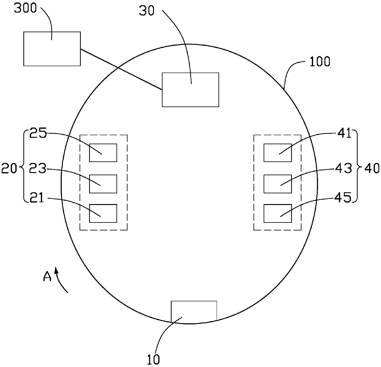
[0026] See also Figure 2 to Figure 4 In the method for forming the multi-curved glass 500 according to the embodiment of the present invention, a multi-curved glass forming device (not shown) is provided to mold the glass substrate 400 into the multi-curved glass 500. The molding device for multi-curved glass includes a molding furnace 100, at least one mold 200 and an air extractor 300. In this embodiment, the thickness of the glass substrate 400 is 0.6-1.2 mm, but it is not limited to this.
[0027] See figure 2 , The forming furnace 100 is a structure with a sealed cavity. The forming furnace 100 includes a conveying mechanism (not shown) and a plurality of relatively independent functional areas 10, 20, 30, 40. In this embodiment, the number of molds 200 is multiple, and they are placed in the functional areas 10, 20, 30, 40, respectively. The multiple functional zones 10, 20, 30, 40 include an interaction zone 10, a heating zone 20, a forming zone 30, and a cooling zone 40 arranged in the forming furnace 100 in sequence. In this embodiment, the functional areas 10, 20, 30, and 40 are arranged in an annular shape in sequence so that the interaction area 10 and the cooling area 40 are adjacent to each other. The interaction zone 10 can alternately communicate with the sealed cavity of the forming furnace 100 and the outside to ensure that the sealed cavity in the forming furnace 100 is in a sealed state when the glass substrate 400 is put in and the formed multi-curved glass 500 is taken out. The transfer mechanism can transfer the mold 200 in each functional area 10, 20, 30, 40 to the next functional area 10, 20, 30, 40 at the same time. In this embodiment, the transfer mechanism rotates along the direction A to transfer the mold 200 in each functional zone 10, 20, 30, 40 to the next functional zone 10, 20, 30, 40. Specifically, each time the transfer mechanism works, the mold 200 in the interaction zone 10 is transferred to the heating zone 20, the mold 200 in the heating zone 20 is transferred to the forming zone 30, and the mold 200 in the forming zone 30 is transferred to the cooling zone 40 and the mold in the cooling zone 40. 200 is transferred to the interactive area 10. The steps of feeding, heating, forming, cooling, and unloading are simultaneously performed in the forming furnace.
[0028] It can be understood that in other embodiments, the interaction area 10 can be divided into two independent functional areas: a loading area and a loading area. The feeding zone, the heating zone 20, the forming zone 30, the cooling zone 40 and the unloading zone are arranged in sequence, and the conveying mechanism moves the conveying mold 200 at this time.
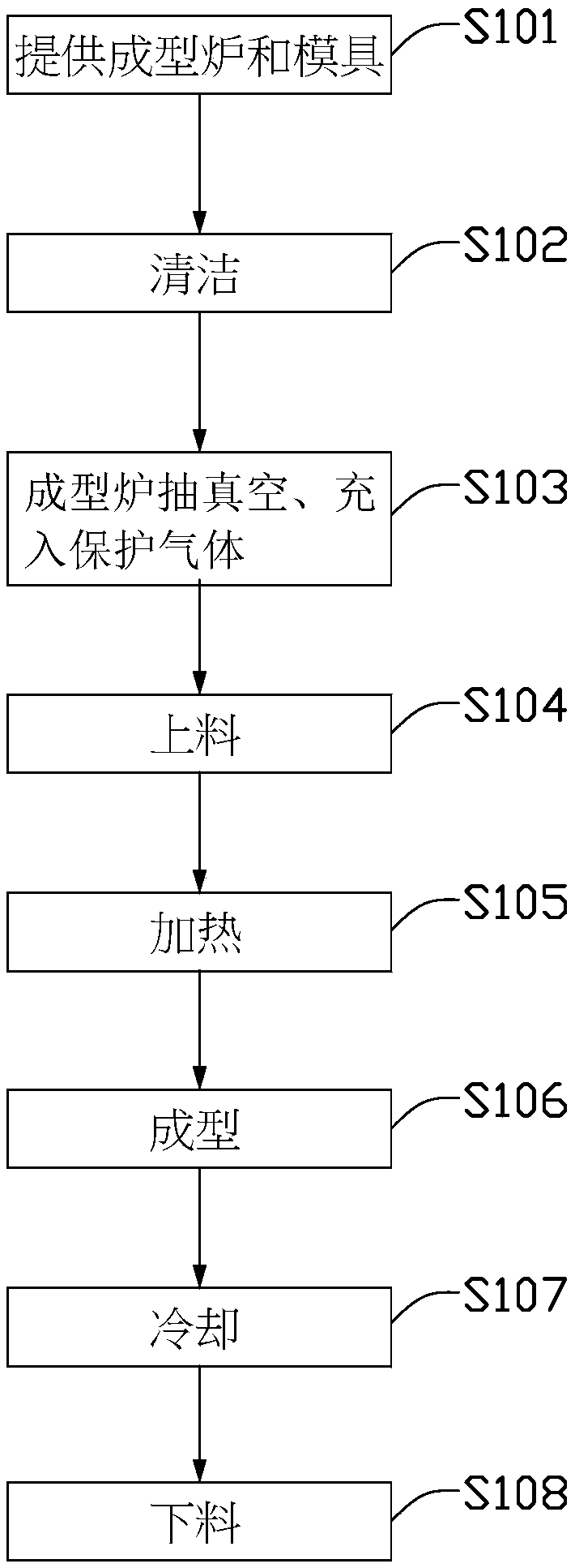
[0029] It can be understood that, in other embodiments, the number of molds 200 may also be one, and the transfer mechanism transfers one mold 200 from one functional area to the next functional area.
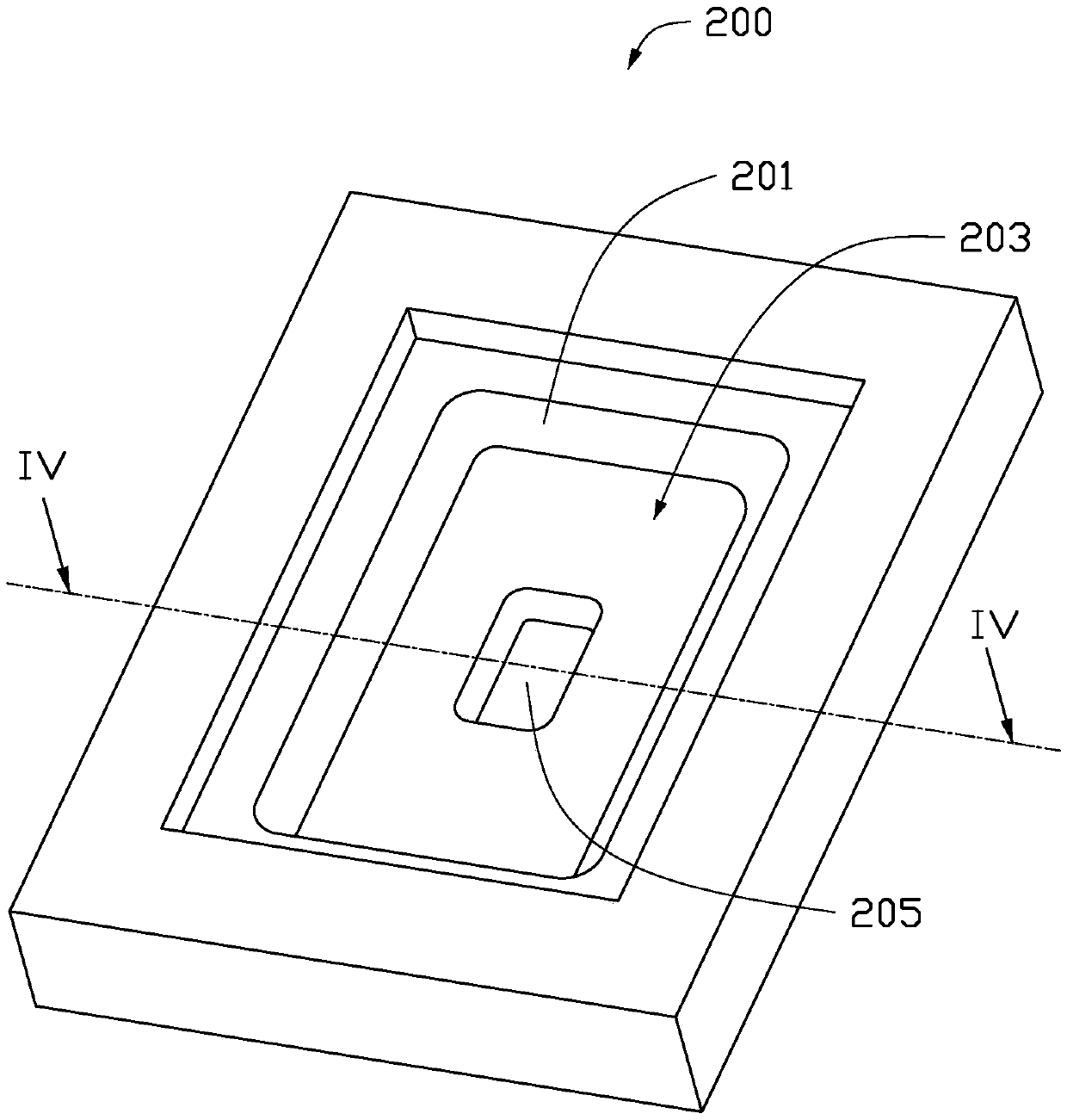
[0030] See image 3 , The mold 200 is made of porous material. In this embodiment, the material of the mold 200 is graphite, but it is not limited thereto. In other embodiments, the material of the mold 200 may also be ceramic. Graphite has the characteristics of low roughness and high temperature resistance, and graphite has many tiny through holes 207.
[0031] The mold 200 is provided with a bearing surface 201, and the bearing surface 201 is used for placing the glass substrate 400. In this embodiment, the supporting surface 201 is provided with a first groove 203 and a second groove 205 imitating the outer surface of the formed polycurved glass 500, but it is not limited thereto. Since the material of the mold 200 is a porous material, the first groove 203 and the second groove 205 have a plurality of through holes 207. It can be understood that in other embodiments, the mold 200 may also be provided with bosses and/or grooves according to the formed multi-curved glass 500, and the number is set according to the curved surface of the multi-curved glass 500. In this embodiment, one mold 200 is used to place one glass substrate 400, but it is not limited to this.
[0032] See figure 1 , The forming method of multi-curved glass 500 includes the following steps:
[0033] In step S101, the aforementioned forming furnace 100 and at least one mold 200 are provided.
[0034] Step S102, cleaning.
[0035] First, the sealed cavity of the molding furnace 100, the mold 200 and the glass substrate 400 are cleaned to improve the molding quality of the glass substrate 400.
[0036] The cleaning of the sealed cavity of the forming furnace 100 includes cleaning the sealed cavity of each functional zone 10, 20, 30, 40 and the sealed cavity of the forming furnace 100 between the functional zones 10, 20, 30, 40.

PUM

no PUM

Description & Claims & Application Information

We can also present the details of the Description, Claims and Application information to help users get a comprehensive understanding of the technical details of the patent, such as background art, summary of invention, brief description of drawings, description of embodiments, and other original content. On the other hand, users can also determine the specific scope of protection of the technology through the list of claims; as well as understand the changes in the life cycle of the technology with the presentation of the patent timeline. Login to view more.

Similar technology patents

Gripping apparatus of tubular pile steel cage

InactiveCN101717036AUniform force pointNot easily deformed
Owner:GUANGDONG SANHE PILE CO LTD

Joint linkage control structure and laboratory central fresh air control system

PendingCN113446676AInnovative designUniform exhaust
Owner:兰州凯博莱特实验室系统工程有限公司

Box culvert jacking device and box culvert jacking method

ActiveCN105803957AEasy to excavateNot easily deformed
Owner:THE FOURTH ENG CO LTD OF CHINA ZHONGTIEMAJOR BRIDGE ENG GRP

Curing chamber with improved air outlet

PendingCN108682783AUniform exhaustImprove uniformity
Owner:TIANNENG BATTERY WUHU

Device and method for preventing welding deformation of supporting burden

ActiveCN102229030AAvoid welding deformationNot easily deformed
Owner:ZOOMLION HEAVY MASCH CO LTD

Classification and recommendation of technical efficacy words

  • Uniform exhaust
  • Not easily deformed

Curing chamber with improved air outlet

PendingCN108682783AUniform exhaustImprove uniformity
Owner:TIANNENG BATTERY WUHU

Joint linkage control structure and laboratory central fresh air control system

PendingCN113446676AInnovative designUniform exhaust
Owner:兰州凯博莱特实验室系统工程有限公司
Why Eureka
Try Eureka