Water distribution and exhaust device for pressure filtration tank, pressure filtration tank and water distribution and exhaust method

A technology of exhaust device and filter tank, which is applied in the direction of loose filter material filter, gravity filter, filter circuit, etc., can solve the problems such as pressure holding in filter tank, gas accumulation, affecting the normal operation of exhaust, etc.

Pending Publication Date: 2020-01-17
DAQING OILFIELD CO LTD +1
View PDF0 Cites 2 Cited by
  • Summary
  • Abstract
  • Description
  • Claims
  • Application Information

AI Technical Summary

Problems solved by technology

However, in the actual production and operation process of this water distribution structure, more shortcomings and problems have been exposed, mainly as follows: firstly, when the filter tank is backwashed ( figure 1 The arrow in the middle indicates the flow direction of the backwash water), and above the water distribution screen is the dead water area 4', that is, the flow path of the backwash water is first to pass through the outlet pipe of the filter tank and enter the bottom of the tank, and the water flows through the litter from bottom to top And the filter material, and finally flow out of the filter tank through the water distribution screen at the top. Above the water distribution screen is a dead water area, and the top of the filter tank cannot be discharged.
This water distribution structure will accumulate a large amount of dirty oil and a small amount of gas in the dead water area. After backwashing, a large amount of pollutants desorbed from the filter ma

Method used


Image

  • Water distribution and exhaust device for pressure filtration tank, pressure filtration tank and water distribution and exhaust method
  • Water distribution and exhaust device for pressure filtration tank, pressure filtration tank and water distribution and exhaust method
  • Water distribution and exhaust device for pressure filtration tank, pressure filtration tank and water distribution and exhaust method

Examples


Embodiment Construction

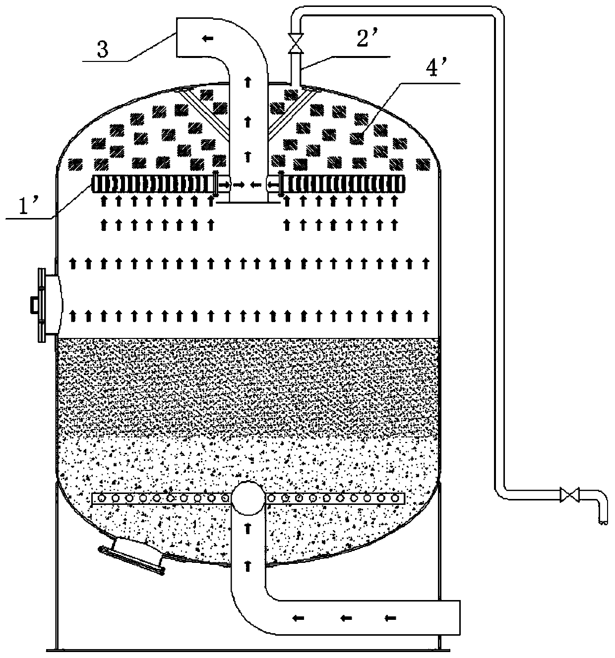
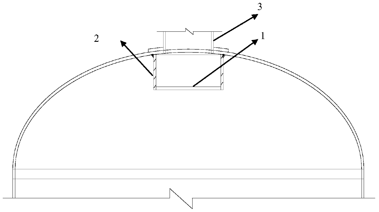
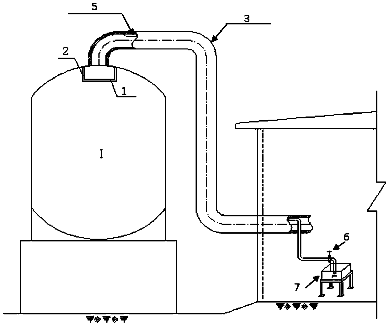
[0023] The present invention aims at the problems existing in the water distribution and exhaust structure and the water distribution and exhaust method on the top of the existing pressure filter tank, and designs a water distribution and exhaust device for the purpose of economy, practicability and high efficiency, which is located at the top of the pressure filter tank At the top, using this device for water distribution and exhaust can improve the treatment efficiency and service life of the filter tank.

[0024] The content of the present invention will be described in more detail below in conjunction with specific examples, and the present invention will be further elaborated, but these examples are by no means limiting the present invention.

[0025] The water distribution and exhaust device for a pressure filter tank provided by the present invention includes a water distribution structure and an exhaust structure, and a pressure filter tank with a diameter of 4 meters m...


PUM


Abstract

The invention discloses a water distribution and exhaust device for a pressure filtration tank, the pressure filtration tank and a water distribution and exhaust method. The water distribution and exhaust device comprises a water distribution structure and an exhaust structure; the water distribution structure is arranged at the top end of the interior of a pressure filtering tank, and is composedof a bottom blocking plate and side blocking plates; a cylinder with an upper opening and a lower opening is formed by the side blocking plates; a plurality of through holes are uniformly distributedin the surface of the cylinder; the bottom blocking plate is arranged at the bottoms of the side blocking plates, and a container with an upper opening and a sealed bottom is formed by the bottom blocking plate and the side blocking plates; the upper opening of the side blocking plates and an top end opening of the pressure filtering tank are in sealing connection, and is communicated with a filtering inlet water dry pipe arranged at the top end opening of the pressure filtering tank. The water distribution and exhaust device is low in manufacturing cost; no blockage is caused, no pressure build-up is induced, no dead water area is formed, uniform water distribution is achieved, thorough exhaust is achieved, no freezing during operation in winter is caused, the treatment efficiency of oilfield pressure filter tanks is improved, and the service life is prolonged.

Description

technical field [0001] The invention relates to the technical field of water treatment equipment, in particular to a pressure filter tank for oilfield produced water, a water distribution and exhaust device and a water distribution and exhaust method arranged on the top of the pressure filter tank. Background technique [0002] In the entire oilfield produced water treatment system, filtration treatment equipment (such as pressure filter tank) is often the final check equipment for water quality treatment, so it is an important key equipment for the oilfield produced water treatment system. The working principle of the pressure filter tank is that the sewage flows through the porous filter material with a certain thickness from top to bottom, and the impurities are left on the filter material or in the pores, so that the sewage is purified. The filter material in the pressure filter tank is usually quartz sand, magnetite or other granular materials. During the filtration pr...

Claims


Application Information

Patent Timeline
IPC IPC(8): B01D24/16B01D24/40B01D24/42C02F1/00B01D35/01C02F103/10
CPCB01D24/167B01D24/405B01D24/42B01D36/001C02F1/001C02F2103/10
Inventor 古文革赵秋实陈忠喜曹振锟舒志明房永徐洪君徐德会
Owner DAQING OILFIELD CO LTD
Why Eureka
Try Eureka