Compressor lubricating oil backflow structure and compressor

A lubricating oil and compressor technology, applied in the field of compressors, can solve the problems of reducing system energy efficiency, disturbance, excessive lubricating oil volume, etc., to achieve the effect of ensuring energy efficiency and reducing disturbance

Pending Publication Date: 2020-04-07
ZHUHAI GREE REFRIGERATION TECH CENT OF ENERGY SAVING & ENVIRONMENTAL PROTECTION
View PDF0 Cites 5 Cited by
  • Summary
  • Abstract
  • Description
  • Claims
  • Application Information

AI Technical Summary

Problems solved by technology

However, this oil return method is to let the lubricating oil fall vertically back to the bottom oil pool, and there are at least two subsequent shortcomings: First, the lubricating oil falling back from the upper bracket can easily fall to the upper end of the motor stator and form a residence, and cannot flow back to the bottom , resulting in a relatively small amount of lubricating oil in the bottom oil pool; second, the dripping process of the lubricating oil falling back from the upper bracket is in an exhaust high-pressure environment, which is easily disturbed by the exhaust refrigerant flow, thereby forming a gas-liquid mixed state, and Discharging from the exhaust pipe of the compressor to the air-conditioning system, on the one hand, this will lead to insufficient lubricating oil in the pump body, and on the other hand, it will easily lead to excessive lubricating oil in the air-conditioning system, thereby reducing the energy efficiency of the system. Based on this, the present invention is proposed

Method used


Image

  • Compressor lubricating oil backflow structure and compressor
  • Compressor lubricating oil backflow structure and compressor
  • Compressor lubricating oil backflow structure and compressor

Examples


Embodiment Construction

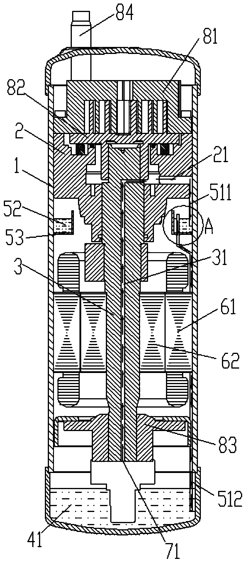
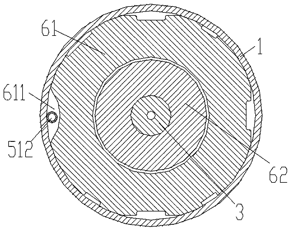
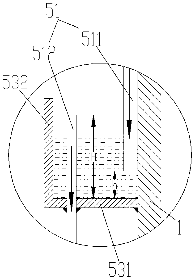
[0020] see in conjunction Figure 1 to Figure 4 As shown, according to the embodiment of the present invention, a compressor lubricating oil return structure is provided, including an outer shell 1, and the outer shell 1 is provided with an upper bracket 2, a crankshaft 3, a lower bracket 83, a fixed scroll 81, a moving Scroll 82 and motor assembly, the bottom of the outer shell 1 is provided with a bottom oil pool 4, the crankshaft 3 is rotatably connected to the upper bracket 2 and the lower bracket 83, and the upper bracket 2 is also used to install The fixed scroll 81 and the movable scroll 82, the motor assembly is used to drive the crankshaft 3 to rotate, and the rotating crankshaft 3 can drive the movable scroll 82 to run (translate) so that the fixed scroll 81 and the moving scroll 82 enters the refrigerant through the intake pipe 84 to form scroll compression. The upper bracket 2 is configured with an oil storage chamber 21. The end of the crankshaft 3 away from the u...


PUM


Abstract

The invention provides a compressor lubricating oil backflow structure and a compressor. The compressor lubricating oil backflow structure comprises an outer housing. An upper support and a crankshaftare arranged in the outer housing. A bottom oil pool is arranged at the bottom of the outer housing; and the crankshaft is connected to the upper support in a rotatable mode. An oil storage cavity isformed in the upper support; the oil storage cavity is used for storing lubricating oil pumped by the crankshaft from the bottom oil pool; an oil return assembly is arranged on the oil storage cavity; and the oil return assembly comprises an oil return pipeline, wherein one end of the oil return pipeline is located in the oil storage cavity, and the other end of the oil return pipeline is locatedunder the liquid level of the lubricating oil in the bottom oil pool. According to the compressor lubricating oil backflow structure and the compressor, disturbance of exhaust refrigerants to the lubricating oil in the lubricating oil backflow falling process can be effectively reduced, then the amount of the lubricating oil carried by the exhaust refrigerants is reduced, and therefore, it is guaranteed that the amount of the lubricating oil in the bottom oil pool is sufficient.

Description

technical field [0001] The invention belongs to the technical field of compressors, and in particular relates to a lubricating oil return flow structure of a compressor and a compressor. Background technique [0002] Scroll compressors have the advantages of simple structure, small size, light weight, low noise, high mechanical efficiency and stable operation. higher requirements. In the scroll compressor, the role of lubricating oil is to cool down and lubricate the friction parts of the motor and each bearing, reduce frictional power consumption, and improve the operating efficiency of the compressor. In the scroll compressor, the lubricating oil is generally located at the bottom of the compressor, and through the oil channel in the oil pump and the crankshaft, the lubricating oil is sent to other parts of the compressor. At the same time, there is an oil storage place on the upper bracket , used to temporarily store the lubricating oil provided to the pump body, where ...

Claims


Application Information

Patent Timeline
Patent Type & Authority Applications(China)
IPC IPC(8): F04C29/02
CPCF04C29/02F04C29/025
Inventor 魏会军董航江律刚李海港单彩侠刘双来方琪马鹏赵玉晨赵豪川
Owner ZHUHAI GREE REFRIGERATION TECH CENT OF ENERGY SAVING & ENVIRONMENTAL PROTECTION
Why Eureka
Try Eureka