Compressor case bleed air structure, bleed air method and aero-engine

A technology for aero-engines and compressors, which is applied in the direction of machines/engines, liquid fuel engines, mechanical equipment, etc., and can solve problems such as incomplete matching, large bleed air channel area, and turbulent flow of bleed air channel

Active Publication Date: 2021-09-14
AECC COMML AIRCRAFT ENGINE CO LTD
View PDF0 Cites 0 Cited by
  • Summary
  • Abstract
  • Description
  • Claims
  • Application Information

AI Technical Summary

Problems solved by technology

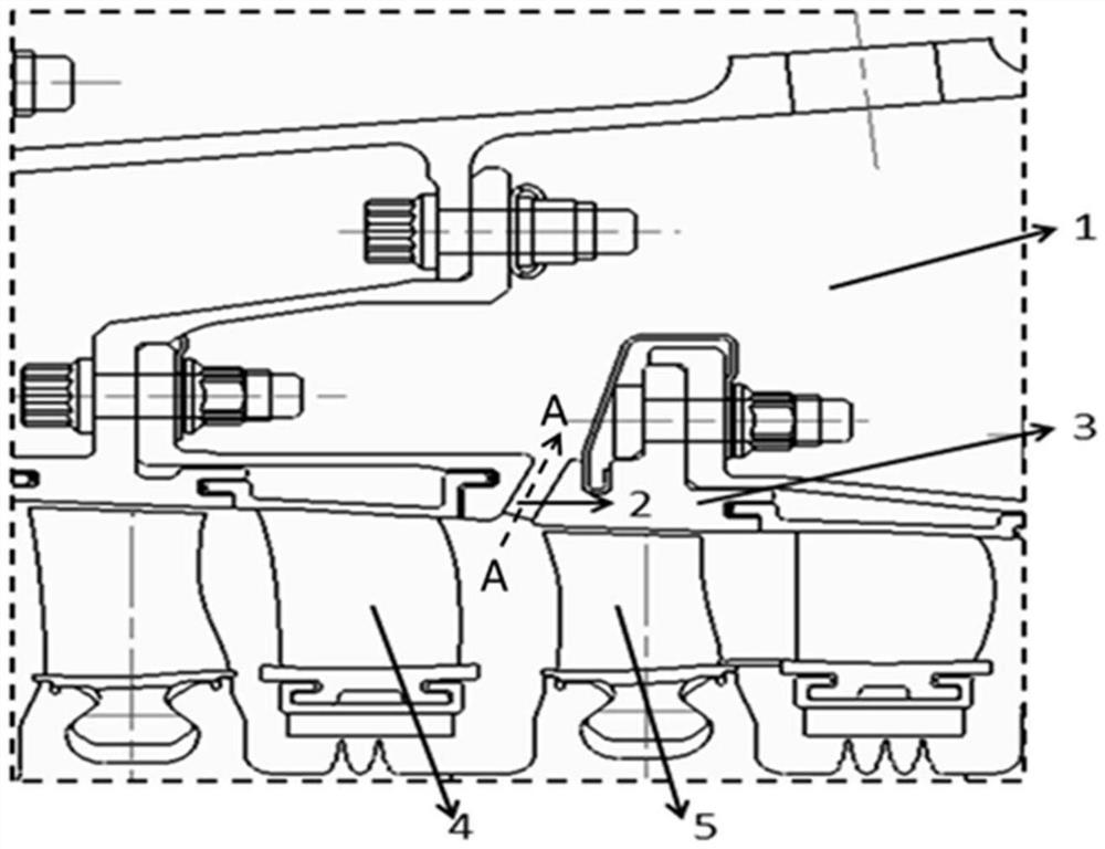
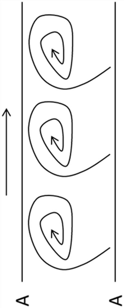
[0005] 1. Without any guidance, the speed and direction of the airflow are formed spontaneously according to the actual flow field conditions, which may cause separation, vortices, etc. in the flow field and affect the flow efficiency, for example figure 2 As shown in the schematic diagram of flow in the bleed air channel A-A section, there will be flow turbulence in the bleed air channel;
[0006] 2. There is a certain deviation between the direction of the airflow and the direction of the bleed air channel, resulting in an incomplete match between the two, and the airflow cannot enter the air collection cavity smoothly;
[0007] 3. Due to the existence of the above defects, in order to achieve sufficient bleed air volume, the required bleed air channel area is relatively large, which will bring difficulties to the structural strength design of the casing

Method used


Image

  • Compressor case bleed air structure, bleed air method and aero-engine
  • Compressor case bleed air structure, bleed air method and aero-engine
  • Compressor case bleed air structure, bleed air method and aero-engine

Examples


Embodiment Construction

[0042] A variety of different implementations or examples for implementing the described subject technical solutions are disclosed below. In order to simplify the disclosure, the following describes the specific examples of each component and arrangement, of course, these are only examples, not limiting the protection scope of the present invention. For example, the description that the first feature described later in the description is formed on or above the second feature may include an embodiment in which the first and second features are formed through direct contact, and may also include an embodiment in which the first and second features are formed between the first and second features. Embodiments of additional features such that there may be no direct relationship between the first and second features. Additionally, reference numerals and / or letters may be repeated in different instances in these disclosures. This repetition is for brevity and clarity and does not i...


PUM


Abstract

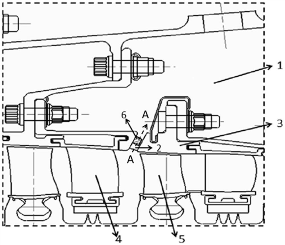
The invention relates to an air-inducing structure of a casing of a compressor, an air-inducing method and an aeroengine. Wherein, the air-inducing structure includes an inner casing, and a plurality of air-inducing passages for connecting the inner casing and the air-collecting cavity are arranged along the circumference of the inner casing; A flow vane includes a leading edge, a trailing edge, a pressure surface and a suction surface, the radius of curvature of the leading edge of the guide vane is not less than the radius of curvature of the trailing edge of the guide vane, and the trailing edge of the guide vane faces toward the The orientation of the bleed air channels is the same. The above bleed air structure, bleed air method, and aeroengine at least include the advantages of high bleed air efficiency, simple structural strength design, efficient and stable operation, and the like.

Description

technical field [0001] The invention relates to an air-inducing structure of an air compressor casing, an air-inducing method and an aero-engine. Background technique [0002] In the field of aero-engine and gas turbine, inter-stage bleed is one of the simplest compressor stability expansion methods. This method is to change the axial partial velocity of the airflow entering the compressor, that is, to change the air flow entering the compressor. That is to say, a certain amount of gas needs to be extracted from the main flow to realize anti-breathing of the compressor or provide gas source for cooling the turbine. [0003] Under the current technical conditions, bleed air is mainly realized by arranging bleed air passages (grooves) on the compressor casing and the rotor drum. The bleed air channel located at the casing is usually directly connected to the gas collection chamber, and the gas in the main flow directly enters the gas collection chamber. The movement of gas ...

Claims


Application Information

Patent Timeline
Patent Type & Authority Patents(China)
IPC IPC(8): F04D29/54
CPCF04D29/541F04D29/545
Inventor 邱毅南长峰李斌曹传军翟志龙
Owner AECC COMML AIRCRAFT ENGINE CO LTD
Why Eureka
Try Eureka