Control method of pressurizing gas water heater and gas water heater

A technology of a gas water heater and a control method, which is applied in the control of pressurized gas water heaters and in the field of gas water heaters, and can solve problems affecting user experience, insufficient gas supply pressure, and insufficient gas pressure, so as to avoid continuous excessive work and ensure temperature and stability The effect of ensuring stability, ensuring pressure and stability

Pending Publication Date: 2020-04-07
QINGDAO ECONOMIC & TECHN DEV ZONE HAIER WATER HEATER +1
View PDF8 Cites 0 Cited by
  • Summary
  • Abstract
  • Description
  • Claims
  • Application Information

AI Technical Summary

Problems solved by technology

However, the combustion effect of gas water heaters will be limited by the gas supply conditions of users' homes. Some users' homes may have problems with gas water heaters not working properly due to insufficient gas supply pressure of the overall pipe network or insufficient gas supply during peak gas consumption, affecting hot water production. The speed and user bathing experience
[0003] At present, the maximum gas pressure in my country is about 3000Pa, but the gas pressure is seriously insufficient during the peak gas consumption, which will inevitably cause the following problems: First, the gas pressure may be lower than 1000Pa during the peak gas consumption, resulting in the failure of the gas water heater to start normally; The working principle of gas water heaters, low air pressure directly affects the speed of hot water outlet; third, the poor stability of air pressure affects the stability of outlet water temperature, which will be directly felt by users during use, greatly affecting user experience
[0004] At present, there are no related gas booster water heater products in the market. When the pressure is low, the ratio of gas to air is only adjusted by controlling the proportional valve, and the pressure stability of the gas behind the proportional valve is improved by increasing the opening of the proportional valve. The effect of this method is very limited when the pressure is below 1000Pa

Method used


Image

  • Control method of pressurizing gas water heater and gas water heater
  • Control method of pressurizing gas water heater and gas water heater
  • Control method of pressurizing gas water heater and gas water heater

Examples


Embodiment 1

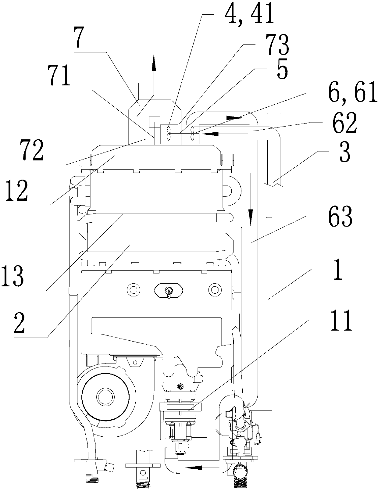
[0044] Such as figure 1 As shown, this embodiment provides a pressurized gas water heater, including a combustion chamber 2 and a gas intake pipeline 3, the gas intake pipeline 3 is connected to the combustion chamber 2, and the gas enters the combustion chamber 2 for combustion, and the combustion chamber 2 is provided with Exhaust gas discharge pipeline 7, a turbine device 4 is arranged in the exhaust gas discharge pipeline 7, a supercharging device 6 is arranged on the gas intake pipeline 3, the turbo device 4 is connected with the supercharging device 6, and the exhaust gas drives the turbine device 4 to rotate , drive the supercharging device 6 to pressurize the gas.

[0045] In this embodiment, the gas water heater with pressurization function includes a heat exchange device 13, a combustion chamber 2, and a gas intake pipeline 3, the gas intake pipeline 3 is connected to the combustion chamber 2, and the gas enters the combustion chamber 2 and burns as a heat exchange d...

Embodiment 2

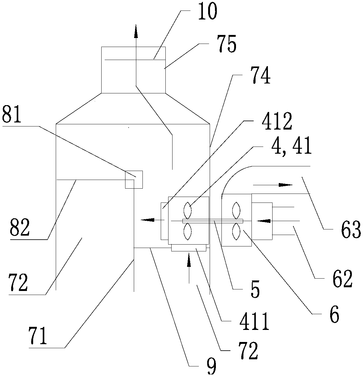
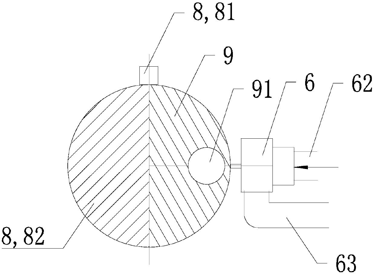
[0074] Such as figure 2 and image 3 As shown, this embodiment is a further solution of Embodiment 1. The turbine device 4 of this embodiment is located in the second discharge chamber 73. The turbine device 4 includes a turbine 41, and an exhaust gas inlet 411 and an exhaust gas outlet 412 are also arranged on it; The side of the turbine device 4 close to the combustion chamber 2 is also provided with a blocking partition 9, the blocking partition 9 and the partition 71 are arranged at a certain angle, and the edge is fixed to the inner wall of the second discharge chamber 73; the blocking partition 9 An opening 91 is provided on the top, and the opening 91 is set correspondingly to the waste gas inlet 411 of the turbine device 4 . In this way, the exhaust gas can be blocked and concentrated to the opening 91 and then enter the turbine device 4, and the exhaust gas passing through the chamber can be utilized to the greatest extent, which is beneficial to control the operati...

Embodiment 3

[0077] Such as Figure 4 As shown, this embodiment is a further limitation of Embodiment 1 or Embodiment 2, and provides a control method for a pressurized gas water heater. The gas water heater includes a combustion chamber 2 and a gas inlet pipeline 3 communicating with it. An exhaust gas discharge pipeline 7 is provided, a turbine device 4 is arranged in the exhaust gas discharge pipeline 7, a supercharging device 6 is arranged on the gas intake pipeline 3, and the turbo device 4 is connected to the supercharging device 6; after the gas water heater is started , if the ignition is unsuccessful, control the exhaust gas in the combustion chamber 2 to flow through the turbine device 4, drive the supercharging device 6 to operate, and pressurize the gas.

[0078] The gas water heater of this embodiment includes a heat exchange device 13, a combustion chamber 2, and a gas intake pipeline 3. The gas intake pipeline 3 is connected to the combustion chamber 2, and the gas enters th...


PUM


Abstract

The invention discloses a control method of pressurizing a gas water heater and the gas water heater. The gas water heater comprises a combustion chamber and a gas inlet pipeline communicating to thecombustion chamber. An exhaust gas discharge pipeline is arranged on the combustion chamber, a turbine device is arranged in the exhaust gas discharge pipeline, a pressurizing device is arranged on the gas inlet pipeline, and the turbine device is connected to the pressurizing device; after the gas water heater is started, if ignition is not successful, exhaust gas in the combustion chamber is controlled to flow through the turbine device to drive the pressurizing device to operate to pressurize gas. The gas water heater can recycle kinetic energy and thermal energy of the exhaust gas, and pressurizes the gas if ignition is not successful, so that the gas inlet pressure and the stability can be guaranteed, it is ensured that the optimum combustion working condition is matched, the water outlet temperature and stability are guaranteed, the energy consumption and the cost can be also reduced, and the user bathing experience is improved greatly.

Description

technical field [0001] The invention belongs to the field of water heaters, and in particular relates to a control method of a pressurized gas water heater and a gas water heater. Background technique [0002] A gas water heater is an instant water heater that burns fuel to transfer heat to water, and is becoming more and more popular among ordinary household users. However, the combustion effect of gas water heaters will be limited by the gas supply conditions of users' homes. Some users' homes may have problems with gas water heaters not working properly due to insufficient gas supply pressure of the overall pipe network or insufficient gas supply during peak gas consumption, affecting hot water production. Speed ​​and user bathing experience. [0003] At present, the maximum gas pressure in my country is about 3000Pa, but the gas pressure is seriously insufficient during the peak gas consumption, which will inevitably cause the following problems: First, the gas pressure...

Claims


Application Information

Patent Timeline
IPC IPC(8): F24H9/20F24H1/12
CPCF24H9/2028F24H1/124
Inventor 郭飞刘云李键王龙强
Owner QINGDAO ECONOMIC & TECHN DEV ZONE HAIER WATER HEATER
Why Eureka
Try Eureka