Industrial furnace heat treatment DCS distributed control equipment

A distributed control and industrial kiln technology, applied in the direction of comprehensive factory control, comprehensive factory control, program control, etc., can solve problems such as damage to clamping parts, achieve the effect of avoiding loosening or damage, and improving the clamping effect

Pending Publication Date: 2020-04-07
吴江中大电器科技有限公司
0 Cites 1 Cited by

AI-Extracted Technical Summary

Problems solved by technology

[0004] The invention provides a DCS distributed control device for heat treatment of industrial furnaces, which has the advantages of avoiding loosening or damage of clamping parts ca...

Method used

Wherein, the bottom end of fine-tuning rod 5 runs through control plate 12 and arc clamp bar 3 and extends to the inside of arc groove 4, and the bottom end of fine-tuning rod 5 is flexibly connected with the top of arc-shaped adjustment block 13, through arc The left and right sides of the shape adjustment block 13 are movably connected with a fine-tuning device 14, which is convenient for secondary clamping of the unclamped position, avoiding the loosening or damage of the clamping parts due to thermal expansion and contraction, and improving the heat treatment efficiency of industrial furnaces. clamping effect.
Wherein, the inside of arc-shaped clamping bar 3 offers and has arc-shaped groove 4, and the interior movable socket of arc-shaped groove 4 is provided with arc-shaped regulating block 13, and arc-shaped regulating block 13 has certain elasticity, thus avoids clamping The heat treatment of industrial furnaces is damaged.
Wherein, the length of forward screw thread 92 and reverse screw thread 94 is identical, and transverse rod 91 is positioned at forward screw thread 92 and reverse screw thread 94 opposite sides and is all fixedly connected with annular sleeve 93, by the positive direction on regulating device 9 Thread 92 and reverse thread 94 are provided with opposite threads, which is convenient to drive the arc-shaped clamping rods 3 on both sides of the heat treatment of the industrial furnace to move in the same direction...

Abstract

The invention relates to the technical field of industrial furnace heat treatment, and discloses industrial furnace heat treatment DCS distributed control equipment which comprises a U-shaped table, atransverse groove is formed in the U-shaped table, a servo motor is fixedly installed on the right side of the interior of the U-shaped table, and a regulation and control device is movably connectedto the interior of the transverse groove and comprises a transverse rod. In the industrial furnace heat treatment DCS centralized and distributed control equipment, opposite threads are arranged through a forward thread and a reverse thread on the regulation and control device; the arc-shaped clamping rods on the two sides of the industrial furnace heat treatment can be conveniently driven to move in the same direction; the stress balance of the two sides of the heat treatment of the industrial furnace is kept; damage to heat treatment of the industrial furnace in the clamping process is prevented; the position of the arc-shaped adjusting block is pushed and moved through the adjusting and controlling plate; fastening of the irregular industrial furnace heat treatment is facilitated; fineadjustment devices are movably connected to the left side and the right side of an arc-shaped adjusting block, so that secondary clamping of the unclamped position is facilitated, the situation thata clamping piece loosens or is damaged due to expansion caused by heat and contraction caused by cold is avoided, and the clamping effect of industrial furnace heat treatment is improved.

Application Domain

Total factory controlProgramme total factory control

Technology Topic

Process engineeringIndustrial furnace +3

Image

  • Industrial furnace heat treatment DCS distributed control equipment
  • Industrial furnace heat treatment DCS distributed control equipment
  • Industrial furnace heat treatment DCS distributed control equipment

Examples

  • Experimental program(1)

Example Embodiment

[0019] The following will clearly and completely describe the technical solutions in the embodiments of the present invention with reference to the accompanying drawings in the embodiments of the present invention. Obviously, the described embodiments are only some, not all, embodiments of the present invention. Based on the embodiments of the present invention, all other embodiments obtained by persons of ordinary skill in the art without making creative efforts belong to the protection scope of the present invention.
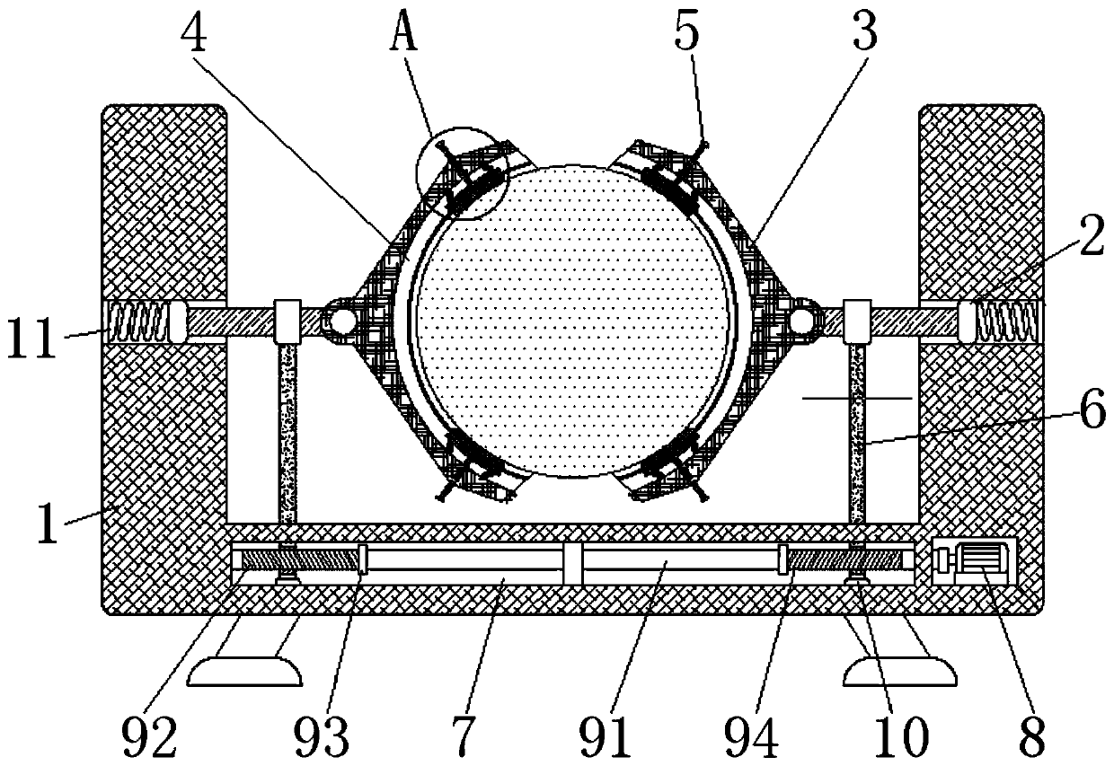
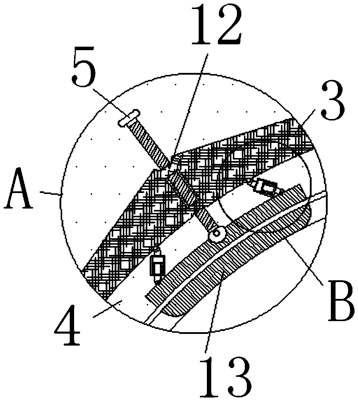
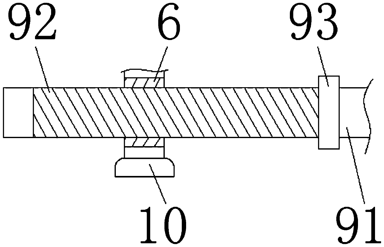
[0020] see Figure 1-4 , a kind of industrial furnace heat treatment DCS distributed control equipment, including a U-shaped table 1, the inside of the U-shaped table 1 is provided with a transverse groove 7, the right side of the U-shaped table 1 is fixedly installed with a servo motor 8, and the inside of the transverse groove 7 A control device 9 is movably connected, and the control device 9 includes a transverse bar 91. The left and right sides of the outer surface of the transverse bar 91 are respectively provided with a forward thread 92 and a reverse thread 94, and the forward thread 92 and the reverse thread 94 are U-shaped. The center line in the vertical direction of the table 1 is symmetrical to each other, the outer surfaces of the forward thread 92 and the reverse thread 94 are threaded with a vertical support part 6, and the bottom end of the vertical support part 6 is fixedly connected with a snap-in block 10, The bottom of the clamp block 10 is movably connected with the bottom of the inner wall of the transverse groove 7, the top of the vertical support part 6 runs through the U-shaped platform 1 and extends to the top of the U-shaped platform 1, and the top of the vertical support part 6 is fixedly connected with a clamping joint. The rod 2 is fixedly connected with an arc-shaped clamping rod 3 on one side of the clamping rod 2 close to the vertical centerline of the U-shaped table 1 .
[0021] Wherein, the forward thread 92 and the reverse thread 94 have the same length, and the transverse rod 91 is fixedly connected with an annular sleeve 93 on the opposite side of the forward thread 92 and the reverse thread 94, through the forward thread 92 on the control device 9 and The reverse thread 94 is provided with opposite threads, which is convenient to drive the arc-shaped clamping rods 3 on both sides of the heat treatment of the industrial furnace to move in the same direction, thereby maintaining the force balance on both sides of the heat treatment of the industrial furnace and preventing the heat treatment of the industrial furnace during the clamping process. cause damage.
[0022] Wherein, the top and the bottom of the arc-shaped clamping rod 3 are fixedly connected with a control plate 12, and the inner thread of the control plate 12 is connected with a fine-tuning rod 5. Furnace heat treatment for fastening.
[0023] Wherein, the interior of the arc-shaped clamping rod 3 is provided with an arc-shaped groove 4, and the interior of the arc-shaped groove 4 is movably sleeved with an arc-shaped adjustment block 13. The arc-shaped adjustment block 13 has a certain degree of elasticity, so as to prevent the industrial furnace from being clamped. Kiln heat treatment is damaged.
[0024] Wherein, the bottom end of the fine-tuning rod 5 runs through the control plate 12 and the arc-shaped clamping rod 3 and extends to the inside of the arc-shaped groove 4. The left and right sides of 13 are movably connected with a fine-tuning device 14, which is convenient for secondary clamping of the unclamped position, avoiding loosening or damage of the clamping parts due to thermal expansion and contraction, and improving the clamping effect of industrial furnace heat treatment .
[0025] Wherein, the left and right sides of arc-shaped adjusting block 13 tops are provided with fine-tuning device 14, and fine-tuning device 14 comprises linkage rod 142, and the bottom of linkage rod 142 is flexibly connected with the top of arc-shaped adjusting block 13, and the top of linkage rod 142 The outer side is movably socketed with a cylinder 141, and the top of the cylinder 141 is fixedly connected with the top of the inner wall of the arc groove 4. The inside of the cylinder 141 is movably socketed with a gasket 144, and the bottom of the gasket 144 is connected with the bottom of the cylinder 141 inner wall. The elastic compression part 143 is fixedly connected.
[0026] Wherein, the right end of the clamping rod 2 runs through the U-shaped platform 1 and extends to the inside of the U-shaped platform 1 , and the right end of the clamping rod 2 is fixedly connected to the right side of the inner cavity of the U-shaped platform 1 through the elastic telescopic member 11 .
[0027] The working steps are as follows: first, the staff waits for the heat treatment of the industrial furnace to be clamped to the middle of the two arc-shaped clamping rods 3, and then starts the servo motor 8 clockwise, and drives the horizontal rod 91 to rotate clockwise through the output shaft of the servo motor 8. At this time, the threads of the forward thread 92 and the reverse thread 94 rotate in opposite directions, and then drive the vertical support portion 6 matched with the forward thread 92 and the reverse thread 94 to move toward each other. When the heat treatment of the clamped industrial furnace is When the shape is irregular, since the arc-shaped adjustment block 130 has a certain degree of elasticity, it can avoid damage to the heat treatment of the industrial furnace during the adherence process, and through the cylinder 141 and the gasket 144 inside the fine-tuning device 14 on both sides of the arc-shaped adjustment block 13 The way of movable connection is convenient for the staff to fine-tune and fasten the heat treatment of the industrial furnace.
[0028] It should be noted that in this article, relational terms such as first and second are only used to distinguish one entity or operation from another entity or operation, and do not necessarily require or imply that there is a relationship between these entities or operations. There is no such actual relationship or order between them. Furthermore, the term "comprises", "comprises" or any other variation thereof is intended to cover a non-exclusive inclusion such that a process, method, article, or apparatus comprising a set of elements includes not only those elements, but also includes elements not expressly listed. other elements of or also include elements inherent in such a process, method, article, or device.
[0029] Although the embodiments of the present invention have been shown and described, those skilled in the art can understand that various changes, modifications and substitutions can be made to these embodiments without departing from the principle and spirit of the present invention. and modifications, the scope of the invention is defined by the appended claims and their equivalents.

PUM

no PUM

Description & Claims & Application Information

We can also present the details of the Description, Claims and Application information to help users get a comprehensive understanding of the technical details of the patent, such as background art, summary of invention, brief description of drawings, description of embodiments, and other original content. On the other hand, users can also determine the specific scope of protection of the technology through the list of claims; as well as understand the changes in the life cycle of the technology with the presentation of the patent timeline. Login to view more.

Similar technology patents

Bearing seat multi-station machining device convenient to fix

PendingCN114536056AImprove targetingImprove clamping effect
Owner:江苏振赋林智能科技有限公司

Metal workpiece punching device with good clamping effect

InactiveCN113084214AImprove clamping effectImprove practicality
Owner:南京鸿音工程技术有限公司

Welding, feeding and conveying device for automatic production of electric water heater heating disc

ActiveCN112139705Aguaranteed symmetryImprove clamping effect
Owner:广东富仕雅热能科技有限公司

Dialysate-free artificial kidney device

InactiveCN114344593AEasy clamping operationImprove clamping effect
Owner:王艳丽

Classification and recommendation of technical efficacy words

  • Improve clamping effect

Machining-stable steel structure cutting device

InactiveCN110369803AImprove clamping effectImprove cutting effect
Owner:重庆宝高实业有限公司

Bill storage device for accountants

ActiveCN112026400AImprove clamping effectavoid folding
Owner:湖北沐桂科技有限公司

Processing device for shearing welded steel pipe

InactiveCN112548198AImprove clamping effectreduce shock
Owner:东台嘉琳铧不锈钢有限公司

Preparation device of environment-friendly alloy new material alloy bar for food mechanical part

PendingCN112846960AImprove clamping effectImprove stability
Owner:SUZHOU RICHMOND ADVANCED MATERIAL TECH TRANSFER CO LTD
Why Eureka
Try Eureka