Eureka AIR delivers breakthrough ideas for toughest innovation challenges, trusted by R&D personnel around the world.

Temperature control technology of laser during continuous measurement

A temperature control and temperature controller technology, applied in non-electric variable control, simultaneous control of multiple variables, control/regulation systems, etc., can solve problems such as laser damage and laser heat generation, improve service life and facilitate heat dissipation , to ensure the effect of the use of the environment

Inactive Publication Date: 2020-04-07
JIANGSU JUNLONG ELECTRIC TECH
View PDF8 Cites 0 Cited by
  • Summary
  • Abstract
  • Description
  • Claims
  • Application Information

AI Technical Summary

Problems solved by technology

[0004] The object of the present invention is to provide a temperature control technology of the laser during continuous measurement, to solve the problem that the existing optical frequency domain reflectometer proposed in the above background technology will generate a large amount of heat during continuous measurement, and the temperature of the laser is too high , it will cause damage to the laser

Method used


Image

  • Temperature control technology of laser during continuous measurement
  • Temperature control technology of laser during continuous measurement

Examples


Embodiment Construction

[0018] The technical solutions in the embodiments of the present invention will be clearly and completely described below in conjunction with the embodiments of the present invention. Apparently, the described embodiments are only some of the embodiments of the present invention, not all of them. Those of ordinary skill in the art can understand the specific meanings of the above terms in the present invention in specific situations.

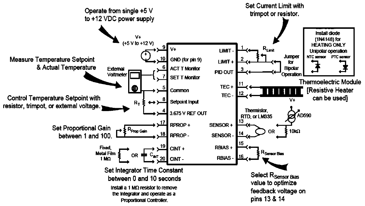
[0019] A temperature control technology for lasers during continuous measurement, the specific steps are as follows: the temperature control part of the laser is completed by a high-performance temperature controller HTC1500, the PI control loop is designed as a bipolar current source, using a resistance temperature sensor and a built-in sensor Bias current, adding a diode to run resistive heaters with unipolar output current, on-board reference voltage simplifies potentiometer control of temperature set point, optional external set point voltage...


PUM


Abstract

The invention relates to a temperature control technology of a laser during continuous measurement. The method comprises the following specific steps that, the temperature control part of the laser iscompleted by a high-performance temperature controller HTC1500, a PI control loop is designed into a bipolar current source, a resistance temperature sensor and a built-in sensor bias current are used, a diode is added, a single-pole output current is used for operating a resistance heater, an onboard reference voltage simplified potentiometer controls a temperature setting point, an external fixed-point voltage can be selected for remote operation, and two monitors are connected with the temperature fixed-point voltage and an actual sensor voltage. According to the temperature control technology of the laser during continuous measurement, the temperature controller is additionally arranged on the laser, codes are written on software to control on-off of the laser, temperature control over the laser can be achieved, and the situation that the laser is damaged and financial losses are caused due to the fact that an optical frequency domain reflectometer generates a large amount of heatduring continuous measurement work is effectively avoided.

Description

technical field [0001] The invention relates to the technical field of high-end equipment manufacturing, in particular to a temperature control technology of a laser during continuous measurement. Background technique [0002] High-end equipment manufacturing industry, also known as advanced equipment manufacturing industry, refers to the industry that produces advanced industrial facilities and equipment with high technology and high added value. Optical frequency domain reflectometer is a high-end equipment with a wide range of applications. laser device. In 1954, the first microwave quantum amplifier was made, and a highly coherent microwave beam was obtained. Except for the free electron laser, the basic working principles of all kinds of lasers are the same. The essential conditions for laser generation are particle number inversion and gain greater than loss, so the essential components in the device include excitation (or pumping) source and working medium with metas...

Claims


Application Information

Patent Timeline
Patent Type & Authority Applications(China)
IPC IPC(8): G05D27/02
CPCG05D27/02
Inventor 朱俊
Owner JIANGSU JUNLONG ELECTRIC TECH
Why Eureka
Eureka Blog
Learn More