Fatigue driving monitoring method and system based on acceleration sensor

An acceleration sensor and fatigue driving technology, applied in instruments, alarms, etc., can solve problems such as large environmental impact, high cost, and positioning failure, and achieve the effect of overcoming specific requirements, improving competitive advantages, and improving accuracy

Active Publication Date: 2020-04-07
深圳市顺禾电器科技有限公司
View PDF6 Cites 1 Cited by
  • Summary
  • Abstract
  • Description
  • Claims
  • Application Information

AI Technical Summary

Problems solved by technology

Because different models have different CAN bus protocols, if you use the CAN bus to obtain the car status, it is only applicable to the specific models of the pre-installation; it cannot be made into a universal product suitable for all models.
The cost of obtaining the status of the car using GPS positioning is relatively high, and it is also greatly affected by the environment (such as weak GPS signals in tunnels causing positioning failure)

Method used


Image

  • Fatigue driving monitoring method and system based on acceleration sensor
  • Fatigue driving monitoring method and system based on acceleration sensor

Examples


Embodiment 1

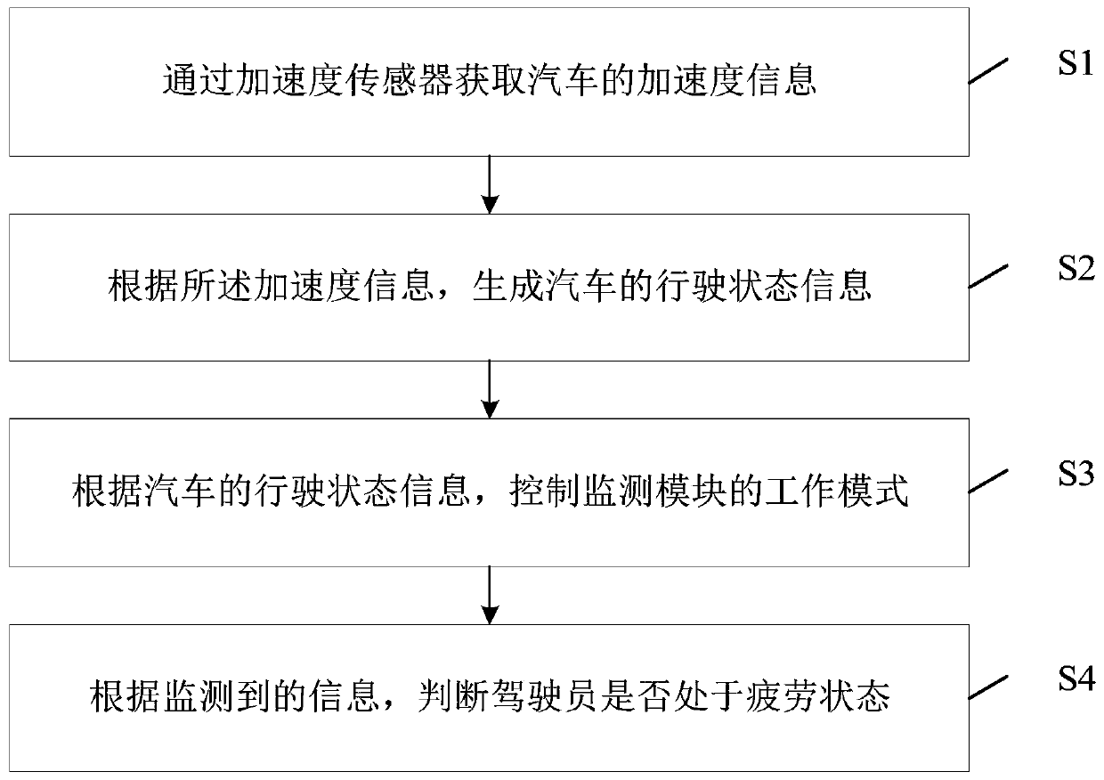
[0041] figure 1 Shown is the flowchart of the fatigue driving monitoring method based on the acceleration sensor provided by the present invention, as figure 1 as shown, figure 1 Shown is the flow chart of the fatigue driving monitoring method based on the acceleration sensor provided by the present invention, including the following steps:

[0042] Step S1, obtaining the acceleration information of the car through the acceleration sensor;

[0043] Specifically, in an embodiment of the present invention, the acceleration sensor adopts the MMA8491Q chip produced by NXP Company. This chip has X, Y, Z three-way sensors, 14-bit AD analog-to-digital converter. The X, Y, and Z three-directional sensors sense the acceleration changes in the lateral, longitudinal, and vertical directions respectively; and convert the results of acceleration changes into digital information through the ADC analog-to-digital converter; output from the IIC interface to the external MCU.

[0044] Step...

Embodiment 2

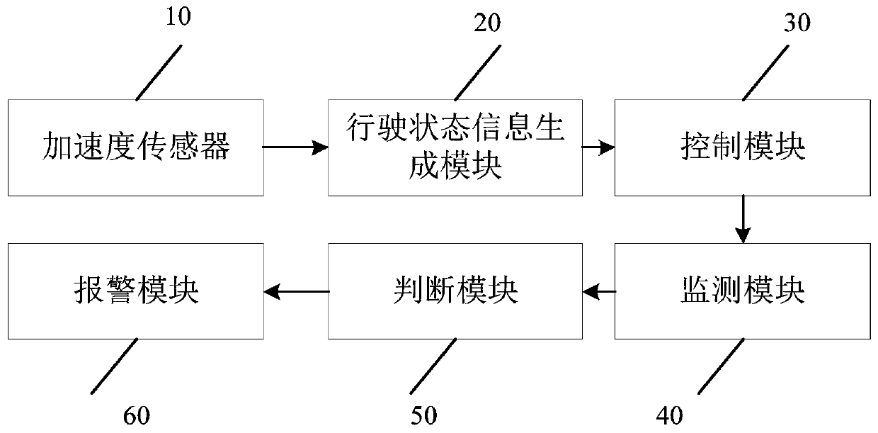
[0053] Based on the same inventive concept, the present invention also provides a fatigue driving monitoring system based on an acceleration sensor, including:

[0054] Acceleration sensor 10, for obtaining the acceleration information of automobile;

[0055] Specifically, in an embodiment of the present invention, the acceleration sensor adopts the MMA8491Q chip produced by NXP Company. This chip has X, Y, Z three-way sensors, 14-bit AD analog-to-digital converter. The X, Y, and Z three-directional sensors sense the acceleration changes in the lateral, longitudinal, and vertical directions respectively; and convert the results of acceleration changes into digital information through the ADC analog-to-digital converter; output from the IIC interface to the external MCU.

[0056] The driving state information generation module 20 is used to generate the driving state information of the automobile according to the acceleration information;

[0057] Specifically, in an embodime...


PUM


Abstract

The invention discloses a fatigue driving monitoring method based on an acceleration sensor. The fatigue driving monitoring method comprises the following steps: S1, obtaining acceleration informationof an automobile through the acceleration sensor; S2, generating driving state information of the automobile according to the acceleration information; S3, controlling the working mode of a monitoring module according to the driving state information of the automobile; and S4, judging whether the driver is in a fatigue state or not according to the monitored information. According to the invention, specific requirements of a CAN bus on a communication protocol are overcome; and the defects that the GPS is weak in signal in a specific area (such as a tunnel) and cannot continuously and stablywork are overcome. Meanwhile, the cost of the scheme is not high; the product manufactured by using the scheme has better competitive advantages.

Description

technical field [0001] The technical field of intelligent driving of the present invention, more specifically, relates to a fatigue driving monitoring method and system based on an acceleration sensor. Background technique [0002] Driving Fatigue Monitoring (DFM: Driving Fatigue Monitoring) is an electronic monitoring device that uses sensors such as cameras to obtain facial features such as the driver's eyes and mouth, and cooperates with specific computer vision algorithms to determine whether the driver is driving fatigued. [0003] This kind of equipment can work normally when the vehicle is moving forward; but when turning, the driver may turn his head to observe the situation outside the vehicle. At this time, the DFM will think that the driver is not paying attention to driving and call the police; or encounter traffic lights At this time, the driver may stop and talk to the people next to him, or turn his head to observe the surrounding environment. At this time, DF...

Claims


Application Information

Patent Timeline
Patent Type & Authority Applications(China)
IPC IPC(8): G08B21/06
CPCG08B21/06
Inventor 杨维美
Owner 深圳市顺禾电器科技有限公司
Why Eureka
Try Eureka