Ion generator and electrostatic eliminator

A technology of ion generator and static eliminator, which is applied in the direction of static electricity and electrical components

Pending Publication Date: 2020-04-07
SHENZHEN HORB TECH CORP LTD
View PDF0 Cites 0 Cited by
  • Summary
  • Abstract
  • Description
  • Claims
  • Application Information

AI Technical Summary

Problems solved by technology

[0008] The purpose of the present invention is to provide a kind of ion generator and stati

Method used


Image

  • Ion generator and electrostatic eliminator
  • Ion generator and electrostatic eliminator
  • Ion generator and electrostatic eliminator

Examples


Embodiment Construction

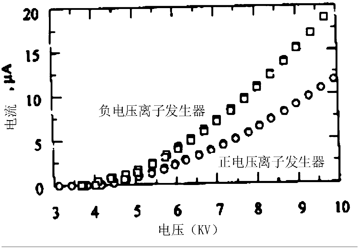
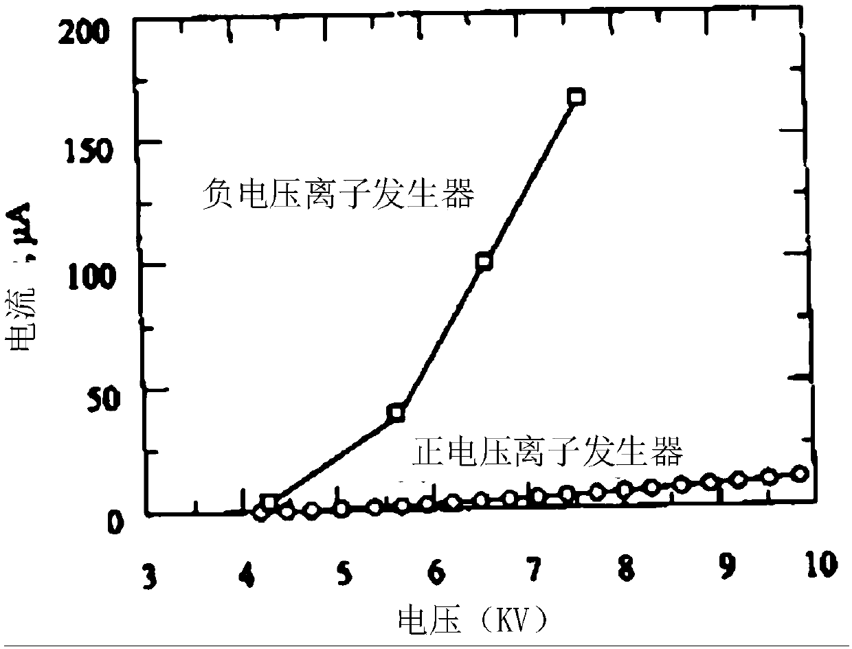
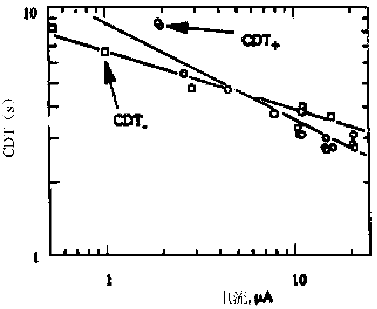
[0031] The ion generator and static eliminator proposed by the present invention will be further described in detail below in conjunction with the accompanying drawings and specific embodiments. Advantages and features of the present invention will be apparent from the following description and claims. It should be noted that all the drawings are in a very simplified form and use imprecise scales, and are only used to facilitate and clearly assist the purpose of illustrating the embodiments of the present invention.

[0032] Embodiments of the present invention are described below through specific examples, and those skilled in the art can easily understand other advantages and effects of the present invention from the content disclosed in this specification. The present invention can also be implemented or applied through other different specific implementation modes, and various modifications or changes can be made to the details in this specification based on different view...


PUM

PropertyMeasurementUnit
Diameteraaaaaaaaaa

Abstract

The invention provides an ion generator and an electrostatic eliminator. The electrostatic eliminator comprises a voltage source device and two ion generators connected with the voltage source device,the two ion generators are oppositely arranged, electrode needles on the two ion generators are parallel to each other, and the tip directions of the electrode needles are the same; each ion generator comprises a base body and at least one electrode needle fixed on the base body, at least one accommodating cavity is formed in each base body, and one electrode needle accommodates in each accommodating cavity; the tail end of each electrode needle is fixed on one base body in one accommodating cavity, and the tip end of each electrode needle extends out of one accommodating cavity and is higherthan the surface of one base body. According to the electrostatic eliminator composed of the ion generators with the needle-cavity structure (namely, the at least one electrode needle is contained inthe at least one accommodating cavity), airflow and ion flow can be transmitted more easily based on the gap between the electrode needle and the at least one accommodating cavity in the needle-cavity structure, and therefore corona discharge can be stably generated in the nitrogen environment.

Description

technical field [0001] The invention relates to the technical field of static elimination, in particular to an ion generator and a static eliminator. Background technique [0002] In order to prevent various disasters caused by electrostatic discharge (ESD), the international scientific and technological circles have realized the safety process of sealing nitrogen gas to prevent fire, explosion and other vicious accidents in an oxygen-free and low-oxygen environment. However, how to realize the continuous operation of the static eliminator under the nitrogen environment is one of the difficulties that must be overcome by the scientific and technological circles. [0003] Sealing nitrogen safety process (also known as nitrogen inerting safety process, sometimes referred to as nitrogen sealing) has been involved in many industrial processes, such as various powder preparation, pharmaceuticals, petrochemical processes, chemical synthesis, ship oil tank cleaning, oil tank depot ...

Claims


Application Information

Patent Timeline
IPC IPC(8): H05F3/04
CPCH05F3/04
Inventor 韩玲玲顾大元孙可平
Owner SHENZHEN HORB TECH CORP LTD
Why Eureka
Try Eureka