
A method for generating phase-shifting pulse width modulation pulses in a digitally controlled switching power supply

A phase-shifting pulse width modulation and numerical control switching technology, applied in the direction of pulse duration/width modulation, etc., can solve the problem of needing large-capacity memory, etc., and achieve the effect of simple circuit structure, rapid control, and convenient control.

Active Publication Date: 2012-07-18
3RD GENERAL DESIGN DEPT CHINA AEROSPACE SCI & IND CORP
View PDF0 Cites 0 Cited by
  • Summary
  • Abstract
  • Description
  • Claims
  • Application Information

AI Technical Summary

Problems solved by technology

[0004] The purpose of the present invention is to solve the problem that a large-capacity memory is required in the method for generating phase-shifting PWM pulses in the existing numerical control system, and to provide a method for generating phase-shifting pulses in a numerically controlled switching power supply, which can generate 0-180° adjustable Phase angle of PWM pulses without mass memory

Method used


Image

  • A method for generating phase-shifting pulse width modulation pulses in a digitally controlled switching power supply
  • A method for generating phase-shifting pulse width modulation pulses in a digitally controlled switching power supply
  • A method for generating phase-shifting pulse width modulation pulses in a digitally controlled switching power supply

Examples


Embodiment 1

[0031] A method for generating phase-shifting pulse width modulation pulses in a numerically controlled switching power supply, comprising the steps of:

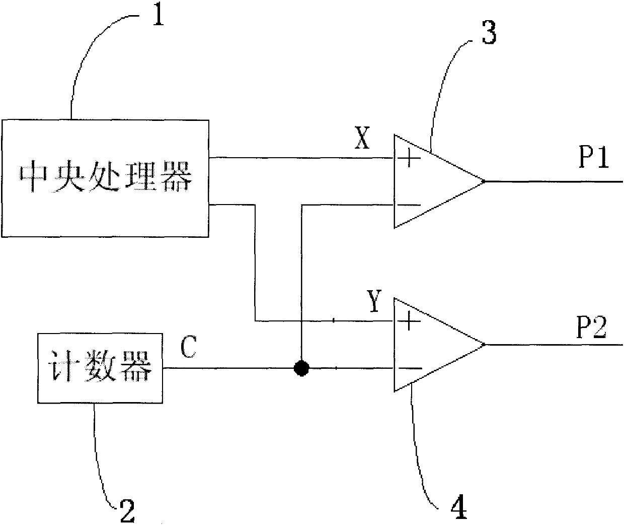
[0032] a) if figure 1 As shown, two comparators 3 and 4 of A and B are set up, and each comparator has two input terminals of positive terminal and negative terminal. When the positive terminal input of A and B comparator is greater than the negative terminal input, the output high level , otherwise output low level;

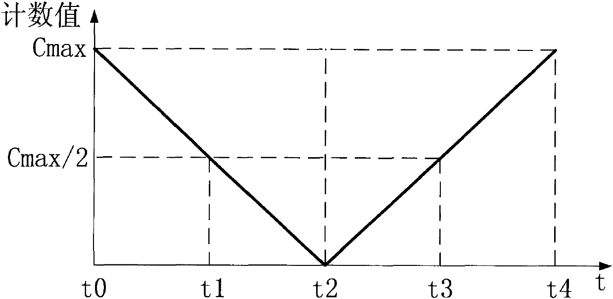
[0033] b) Connect the negative terminals of the two comparators A and B to the output terminal of a counter 2 respectively, and set the counter cycle counting. The counting process in the single working cycle T of the counter is: the counting value C starts from the counting upper limit value Cmax Count down to 0, and then count up to Cmax from 0. Here, Cmax can be determined according to the counting frequency of the counter and the required pulse period. When the required pulse period is T and the counting ...

Embodiment 2

[0049] In the first embodiment, the method of how to generate the 0° phase-shift angle pulse has been described, and the method for how to generate the 180° phase-shift angle pulse is described below, which includes the following steps:

[0050] a): if figure 1 As shown, two comparators 3 and 4 of A and B are set up, and each comparator has two input terminals of positive terminal and negative terminal. When the positive terminal input of A and B comparator is greater than the negative terminal input, the output high level , otherwise output low level;

[0051] b): Connect the negative terminals of the two comparators A and B to the output terminal of a counter 2 respectively, and set the counter to cycle count. The counting process in the single working cycle T of the counter is: the counting value C starts from the counting upper limit value Cmax counts down to 0, and then counts up to Cmax from 0. Here, Cmax can be determined according to the counting frequency of the coun...

Embodiment 3

[0066] This embodiment describes how to generate a group of phase-shifted pulse width modulation pulses with a phase-shift angle of 120°.

[0067] It includes the following steps:

[0068] a): if figure 1 As shown, two comparators 3 and 4 of A and B are set up, and each comparator has two input terminals of positive terminal and negative terminal. When the positive terminal input of A and B comparator is greater than the negative terminal input, the output high level , otherwise output low level;

[0069] b): Connect the negative terminals of the two comparators A and B to the output terminal of a counter 2 respectively, and set the counter to cycle count. The counting process in the single working cycle T of the counter is: the counting value C starts from the counting upper limit value Cmax counts down to 0, and then counts up to Cmax from 0. Here, Cmax can be determined according to the counting frequency of the counter and the required pulse period. When the required pul...


PUM


Abstract

The invention relates to a digitally controlled switching power supply, and specifically discloses a method for generating phase-shifting pulse width modulation pulses in a digitally controlled switching power supply. Set up two comparators A and B, the negative terminals of the two comparators are respectively connected to the output terminal of a counter, and the counter is set to count circularly. The count value C first counts down from the counting upper limit value C max to 0, and then from 0 Count up to C max; start the counter again, calculate the comparison value X and Y, and send them to the positive terminals of the two comparators A and B respectively synchronously. The invention compares the comparison value generated by the formula with the count value of decrement and increment, controls the high and low levels of the output pulse, solves the problem that a large-capacity memory is needed in the method of generating phase-shifting PWM pulses in the numerical control system, and can generate 0 to 180 ° PWM pulse with adjustable phase shift angle, and the PWM pulse is directly generated by the comparator, the control is fast, the circuit structure is simple, the hardware is less, and the resources of the central processing unit do not need to be occupied.

Description

technical field [0001] The invention relates to a digitally controlled switching power supply, in particular to a method for generating phase-shifting pulse width modulation pulses in a digitally controlled switching power supply. Background technique [0002] The method of phase-shift control is widely used in switching power supplies. Early analog-controlled switching power supplies use dedicated control chips, which can generate phase-shifted pulse width modulation pulses (hereinafter referred to as PWM pulses). With the continuous development of digital technology, many engineers and technicians have introduced numerical control chips into the control field of switching power supplies, but how to generate 0-180° phase-shifted pulse width modulation pulses (PWM pulses) is a key technology that needs to be solved . Wang Cong, Wu Hongjie, and Wei Weihua published an article "All-digital PWM controller for DC / DC full-bridge converter" in "Power Electronics Technology" No. 6...

Claims


Application Information

Patent Timeline
Patent Type & Authority Patents(China)
IPC IPC(8): H03K7/08
Inventor 谢孟
Owner 3RD GENERAL DESIGN DEPT CHINA AEROSPACE SCI & IND CORP
Learn More