Side discharge spiral classifier for mineral dressing

A discharge screw and classifier technology, applied in solid separation, wet separation, sieve and other directions, can solve the problems of adjusting screw design protection structure, adjusting screw thread damage, inconvenience in practical use, etc., to reduce thrust, lighten The effect of thread damage and easy adjustment

Inactive Publication Date: 2020-04-10
嘉兴新博信息科技有限公司
View PDF8 Cites 4 Cited by
  • Summary
  • Abstract
  • Description
  • Claims
  • Application Information

AI Technical Summary

Problems solved by technology

[0005] Aiming at the above-mentioned shortcomings existing in the prior art, the present invention provides a side-discharge spiral classifier for mineral processing, which can effectively overcome the problem in the prior art that the adjusting screw is not designed after the angle adjustment of the spiral classifier. Protective structure, the thread of the adjusting screw is easy to be damaged during mineral processing and grading, and needs to be replaced and repaired after a period of use, resulting in high grading costs and inconvenient practical use. At the same time, the grading gears of the spiral classifier are fixed and cannot be adjusted. The problem

Method used


Image

  • Side discharge spiral classifier for mineral dressing
  • Side discharge spiral classifier for mineral dressing
  • Side discharge spiral classifier for mineral dressing

Examples


Embodiment 1

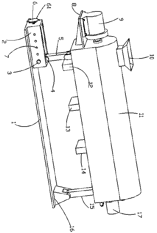
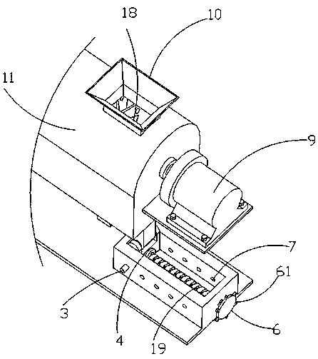
[0032] Such as figure 1 and figure 2 As shown, a side discharge spiral classifier for mineral processing in this embodiment includes a base plate 1, a motor 9, a feed hopper 10, a frame 11 and a spiral body 19, and the left and right ends of the top of the base plate 1 are respectively fixedly connected with loops. The word frame 2 and the fixed U-shaped block 16, the back word frame 2 are threadedly connected with a threaded rod 19 through a threaded hole, and the outer end of the threaded rod 19 is fixedly connected with a rotating structure. Push rod 61 is arranged, and the inner end of threaded rod 19 is rotatably connected with movable U-shaped block 4 through fixedly connected bearings, and a limit structure is arranged between the movable U-shaped block 4 and the back frame 2, and the limit structure includes lock pin 3 and adjustment Hole 7, the front and rear side walls of the back frame 2 are evenly provided with adjustment holes 7, the lock pin 3 passes through th...

Embodiment 2

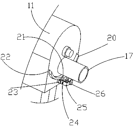
[0035] Embodiment two is a further improvement on embodiment one. Such as figure 1 , 3 , 4 and 5, a feed hopper 10 is fixedly connected to the through hole at the left end of the top of the frame 11, a mounting plate 8 is fixedly connected to the left end of the frame 11, and a motor 9 is fixedly installed on the top of the mounting plate 8, and the motor 9 is connected to the external power supply Electricity 1 connection, the output end of the motor 9 is fixedly connected with a spiral body 19, and the two ends of the spiral body 19 are fixedly connected with the frame 11 through fixedly connected bearings, and the lower end of the grading sieve plate of the frame 11 is uniformly provided with a small discharge hole 27 , medium discharge hole 28 and large discharge hole 29, the right end of the frame 11 is provided with an arc groove 22, an arc plate 20 is slidably connected in the arc groove 22, and the arc plate 20 is uniformly provided with a small The through hole 201,...


PUM


Abstract

The invention discloses a side discharge spiral classifier for mineral dressing, and relates to the technical field of spiral classifiers. The side discharge spiral classifier comprises a bottom plate, wherein the bottom plate is provided with a concentric-square-shaped frame and a fixed U-shaped block; the concentric-square-shaped frame is provided with a threaded rod; the outer end of the threaded rod is provided with a rotating structure; the threaded rod is provided with a movable U-shaped block; a limiting structure is arranged between the movable U-shaped block and the concentric-square-shaped frame; the movable U-shaped block is provided with a rotary supporting leg; the rotary supporting leg is connected with a frame; the fixed U-shaped block is provided with a fixed supporting leg; the fixed supporting leg is connected with the frame; the frame is provided with a feed hopper; the frame is provided with a mounting plate; the mounting plate is provided with a motor; the motor isprovided with a spiral body; the frame is provided with small-sized discharge holes, medium-sized discharge holes and large-sized discharge holes; the frame is provided with an arc-shaped groove; thearc-shaped groove is provided with an arc-shaped plate; the arc-shaped plate is provided with small-sized through holes, medium-sized through holes and large-sized through holes; the arc-shaped plateis provided with an L-shaped plate; and the frame is provided with a large material outlet pipe and the fixed U-shaped block. By using the side discharge spiral classifier, the thrust force of the movable U-shaped block to the threaded rod is reduced; the thread damage of the threaded rod is alleviated; the replacement and maintenance frequency is decreased; the classification cost is decreased;and the side discharge spiral classifier is convenient for actual use.

Description

technical field [0001] The invention relates to the technical field of spiral classifiers, in particular to a side discharge spiral classifier for mineral processing. Background technique [0002] Spiral classifier is one of the equipment for beneficiation. The spiral classifier is a kind of equipment for mechanical classification based on the principle that the specific gravity of solid particles is different, so the speed of sedimentation in the liquid is different. Then the coarse material is screwed into the feed port of the mill by the spiral blade, and the filtered fine material is discharged from the overflow pipe. The spiral classifier is referred to as the classifier. Spiral, submerged single-screw and double-screw classifiers. The classifier is mainly composed of a transmission device, a spiral body, a tank body, a lifting mechanism, a lower support (bearing bush) and an ore discharge valve. The spiral classifier is widely used in mineral processing plants. It c...

Claims


Application Information

Patent Timeline
Patent Type & Authority Applications(China)
IPC IPC(8): B03B5/52B03B11/00B03B7/00B07B1/46
CPCB03B5/52B03B7/00B03B11/00B07B1/4609
Inventor 张红卫
Owner 嘉兴新博信息科技有限公司
Why Eureka
Try Eureka