A side arm type 3D sand printing equipment

A technology of printing equipment and machine arm, which is applied in the field of side-mounted machine arm type 3D sand printing equipment, can solve the problems of low printing efficiency and cumbersome control process, and achieve simple structure, improved quality, improved efficiency and easy operation Effect

Active Publication Date: 2021-08-24
郑州中兴三维科技有限公司
View PDF10 Cites 0 Cited by
  • Summary
  • Abstract
  • Description
  • Claims
  • Application Information

AI Technical Summary

Problems solved by technology

[0005] In the above technical solution, a sliding mechanism is set above the sand box for spraying and printing, and the smoothing mechanism slides on the same track, which is prone to printing failures, low printing efficiency, and cumbersome control process

Method used


Image

  • A side arm type 3D sand printing equipment
  • A side arm type 3D sand printing equipment
  • A side arm type 3D sand printing equipment

Examples


Embodiment 1

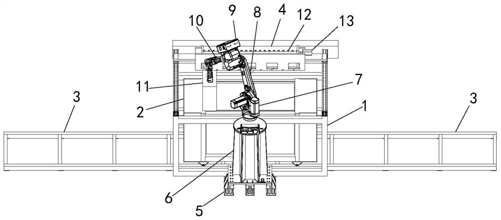
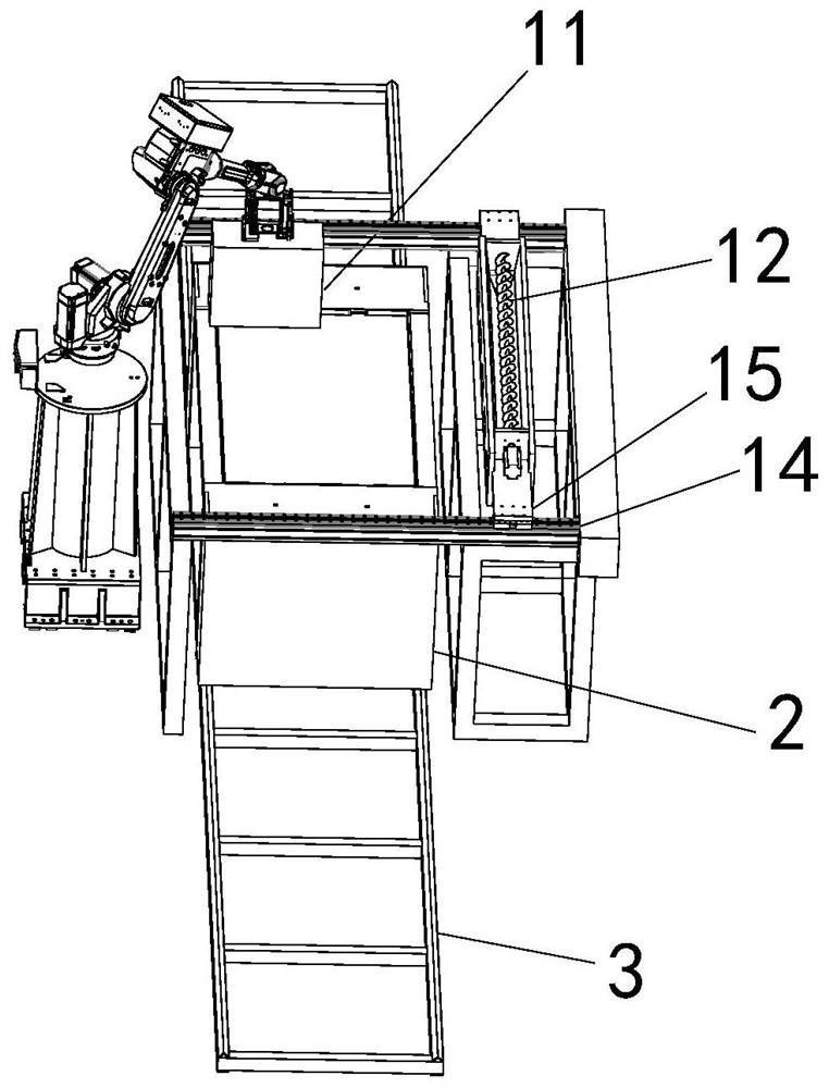
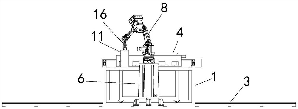
[0038] like Figure 1-5 As shown, a side-mounted arm type 3D sand mold printing equipment; including a frame body 1, a sand box 2, and a slideway 3; It is a rectangular structure; the top of the slideway 3 is slidably connected to the sand box 2; two parallel slide rails 14 are arranged on both sides of the top of the frame body 1, and two slide rails 14 are matched and connected with two sliders 15, a smoothing mechanism 4 is connected between the two sliders 15; one side of the frame body 1 is provided with a machine arm structure, and the machine arm structure includes a base 5, and a main arm 6 is connected above the base 5 1. A turntable is connected above the main arm 6, and a boom 8 is connected above the turntable. The boom 8 is provided with a rotating motor 7 to drive the boom 8 to rotate; the top of the boom 8 is connected to a forearm 10, so The other end of the small arm 10 is connected to a connecting arm 16 , and the other end of the connecting arm 16 is connec...

Embodiment 2

[0049] A side-mounted arm type 3D sand mold printing equipment; including a frame body 1, a sand box 2, and a slideway 3; the inside of the frame body 1 near the bottom is penetrated with the slideway 3, and the slideway 3 is a rectangular structure The sand box 2 is slidably connected to the top of the slideway 3; two parallel slide rails 14 are arranged on both sides of the top of the frame body 1, and two slide rails 14 are matched and connected with two slide blocks 15, so A smoothing mechanism 4 is connected between the two sliders 15; one side of the frame body 1 is provided with a machine arm structure, and the machine arm structure includes a base 5, and the main arm 6 and the main arm 6 are connected above the base 5 A turntable is connected above the main arm 6, and a boom 8 is connected above the turntable, and the boom 8 is provided with a rotating motor 7, which drives the boom 8 to rotate; the top of the boom 8 is connected with a small arm 10, and the small arm ...


PUM


Abstract

The invention discloses a side-mounted machine arm type 3D sand mold printing equipment; it includes a frame body, a sand box, and a slideway; the inside of the frame body near the bottom is penetrated with the slideway, and the slideway is a rectangular structure; The sand box is slidably connected above the slideway; two parallel slide rails are arranged on both sides of the top of the frame body, and the two slide rails are matched and connected with two sliders, and the two sliders are connected There is a smoothing mechanism; one side of the frame body is provided with a machine arm structure, the machine arm structure includes a base, a main arm is connected above the base, a turntable is connected above the main arm, and a large arm is connected above the turntable, The big arm is provided with a rotating motor to drive the big arm to rotate; the present invention prints by setting the side-mounted machine arm and connecting the printing nozzle, avoiding printing through the slide rail together with the smoothing mechanism, and separately executing the printing job, increasing the printing efficiency.

Description

technical field [0001] The invention belongs to the technical field of sand mold 3D printing equipment, and in particular relates to a side-arm type 3D sand mold printing equipment. Background technique [0002] Sand mold 3D printing uses droplet jetting technology to print sand first, and then selectively spray viscous fluid on the sand surface, so that the casting sand is bonded to each other to form the cross section of the part, and then continuously circulate sand and In the process of spraying the binder, the area where the fluid is finally sprayed is bonded to form a three-dimensional sand mold due to the drying of the fluid, which realizes the rapid additive manufacturing of sand molds for casting. [0003] When printing, the existing 3D sand printers generally use a sliding structure on the top of the sand box, and a sliding nozzle on the sliding mechanism to achieve repeated printing work; however, this printing method needs to work successively with the sand and g...

Claims


Application Information

Patent Timeline
Patent Type & Authority Patents(China)
IPC IPC(8): B22C9/02B33Y30/00
CPCB22C9/02B33Y30/00
Inventor 刘中兴吴阳王洪毅刘印
Owner 郑州中兴三维科技有限公司
Why Eureka
Try Eureka