
Synchronous belt transmission vibration reduction system of unmanned helicopter

A technology of synchronous belt transmission and unmanned helicopters, which is applied in the field of unmanned aerial vehicles, can solve the problems of high vibration amplitude of the whole machine, the inability to isolate secondary vibrations, and easy damage to unmanned helicopters, etc., and achieve the effect of reducing secondary vibrations

Pending Publication Date: 2020-04-10
河北春玖智能科技有限公司
View PDF0 Cites 1 Cited by
  • Summary
  • Abstract
  • Description
  • Claims
  • Application Information

AI Technical Summary

Problems solved by technology

[0002] Whether in the military or civilian fields, unmanned helicopters are the most widely used compared with other types of rotorcraft. At present, unmanned helicopters of practical level generally use fuel engines as power sources, so there are problems due to the vibration of the engine itself. As a result, the vibration amplitude of the whole machine is relatively high, which cannot meet the operating environment of unmanned helicopter flight control systems and other related precision electronic equipment.
At the same time, the high-frequency and high-energy vibration of the engine can easily damage the key components of the unmanned helicopter, seriously affecting the flight safety of the unmanned helicopter
In response to the above problems, two methods are generally used to reduce the impact from the engine vibration source. One is to use the synchronous belt scheme for the first-stage deceleration of the rotor. This scheme can reduce the high-frequency / Large-scale vibration, but it is impossible to isolate the secondary vibration reflected on the tension of the first-level synchronous belt due to the dynamic change of the power required by the rotor; the second is to adopt the flexible body coupling scheme, which greatly reduces the The vibration effect of the engine, but this solution can only be used in the layout form of direct transmission of engine power, and cannot be used in other forms of power transmission vibration reduction

Method used

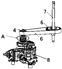

Image

  • Synchronous belt transmission vibration reduction system of unmanned helicopter
  • Synchronous belt transmission vibration reduction system of unmanned helicopter

Examples


Embodiment Construction

[0013] Below in conjunction with accompanying drawing, the present invention will be further described:

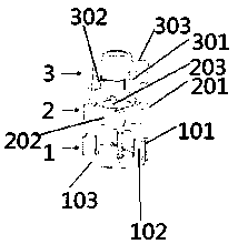
[0014] Such as figure 1 with figure 2 As shown, the unmanned helicopter synchronous belt drive damping system includes an input connection seat 1 and an output connection seat 3, the input connection seat 1 is fixedly connected to one end of the output shaft of the engine 8, and it includes a lower seat surface 103 and a lower seat surface fixedly connected to 103 four input drive teeth 101 on the upper edge. The output connection seat 3 includes an upper seat surface 303 and four output transmission teeth 301 on the lower edge of the upper seat surface 303 . A flexible body 2 is installed between the input connection seat 1 and the output connection seat 3 , and the flexible body 2 includes a circular body 203 and a plurality of buffer pads 201 connected outside the circular body 203 . The input transmission teeth 101, the buffer pad 201 and the output transmission te...


PUM


Abstract

The invention discloses a synchronous belt transmission vibration reduction system of an unmanned helicopter. The system is arranged between an output shaft of an engine and a rotor shaft and comprises an input connecting seat and an output connecting seat, wherein the input connecting seat is fixedly connected with the output shaft of the engine and connected with the output connecting seat through a flexible body, the output connecting seat is fixedly connected with an output wheel, and the output wheel is connected with an input wheel on the rotor shaft through a belt. The vibration reduction system can overcome vibration caused by belt tension in the acceleration and deceleration process, is not limited by the direct transmission layout form, and is suitable for various transmission modes and good in using effect.

Description

technical field [0001] The invention relates to the field of unmanned aerial vehicles, in particular to an unmanned helicopter synchronous belt transmission vibration reduction system. Background technique [0002] Whether in the military or civilian fields, unmanned helicopters are the most widely used compared with other types of rotorcraft. At present, unmanned helicopters of practical level generally use fuel engines as power sources, so there are problems due to the vibration of the engine itself. As a result, the vibration amplitude of the whole machine is relatively high, which cannot meet the operating environment of unmanned helicopter flight control systems and other related precision electronic equipment. At the same time, the high-frequency and high-energy vibration of the engine is easy to damage the key components of the unmanned helicopter, seriously affecting the flight safety of the unmanned helicopter. In response to the above problems, two methods are gen...

Claims


Application Information

Patent Timeline
Patent Type & Authority Applications(China)
IPC IPC(8): B64C27/12
CPCB64C27/12B64C2027/125
Inventor 刘志高陈立新
Owner 河北春玖智能科技有限公司
Learn More