Brazed honeycomb panel internal floating roof storage tank

An internal floating roof storage tank, honeycomb panel technology, applied in the direction of container, packaging, transportation and packaging, can solve the problems of floating tray sinking tray or chuck, storage tank is not easy to enlarge, high construction requirements, to eliminate gas space , the effect of reducing the risk of fire and explosion, and reducing air pollution

Active Publication Date: 2020-04-10
CHANGZHOU LIDAO METALLIC MATERIAL MFG
View PDF7 Cites 6 Cited by
  • Summary
  • Abstract
  • Description
  • Claims
  • Application Information

AI Technical Summary

Problems solved by technology

[0004] However, floating roof storage tanks also have disadvantages. Compared with vaulted roof tanks, the consumption of steel plates is relatively large, and the construction requirements are high; compared with floating roof tanks, maintenance is inconvenient, and storage tanks are not easy to enlarge. There is also a fatal weakness in the tank: the floating plate has sinking or chucking
There are many reasons for sinking or chucking, in addition to the influence of climate change, tank foundation settlement, tank deformation and other factors; the floating plate is also subject to oil corrosion and oil temperature during long-term frequent operation. Due to the impact of the change, the geometric shape and size of the floating plate change, and the buoyancy is different in different places, causing the tilting, or the floating plate is corroded and has through holes, and oil leakage causes the sinking plate

Method used


Image

  • Brazed honeycomb panel internal floating roof storage tank
  • Brazed honeycomb panel internal floating roof storage tank
  • Brazed honeycomb panel internal floating roof storage tank

Examples


specific Embodiment

[0030] The following will clearly and completely describe the technical solutions in the embodiments of the present invention with reference to the drawings in the embodiments of the present invention. Obviously, the described embodiment is only one embodiment of the present invention, not all embodiments. Based on the embodiments of the present invention, all other embodiments obtained by persons of ordinary skill in the art without making creative efforts belong to the protection scope of the present invention. Specific examples are as follows:

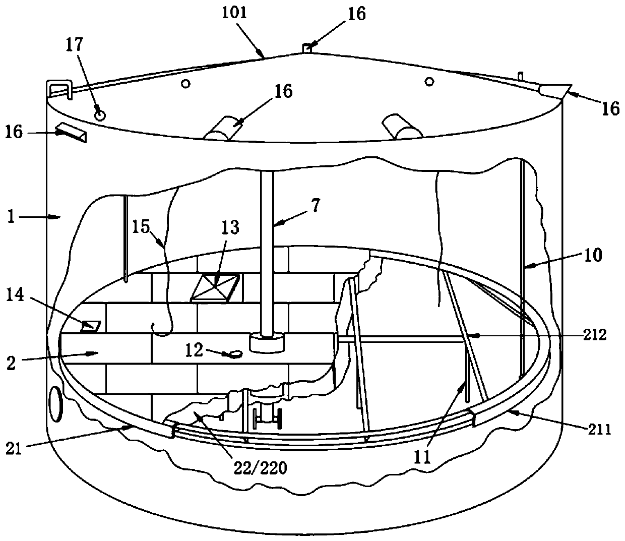
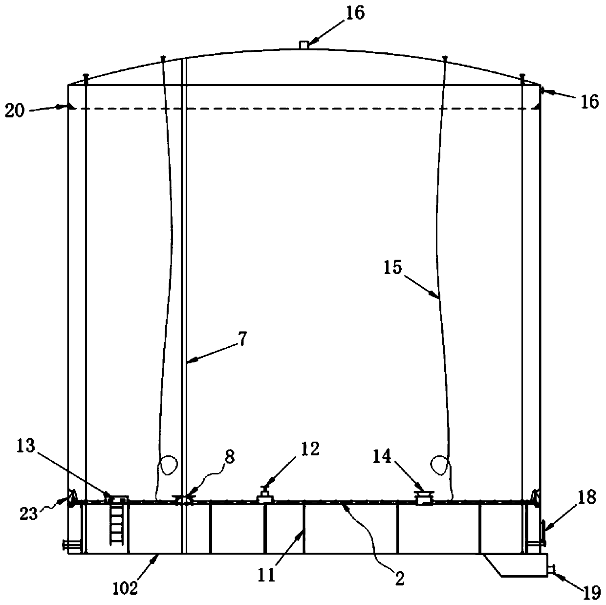
[0031] A kind of brazed honeycomb panel internal floating roof storage tank, such as figure 1 and figure 2 As shown, it includes a tank body 1 and a floating disc 2 slidingly arranged inside the tank body 1. The floating disc 2 includes a floating disc skeleton 21, a floating cabin structure 22 and a sealing ring plate structure 23; the floating disc skeleton 21 includes an annular The main frame 211 and the reticular support fra...


PUM


Abstract

The invention discloses a brazed honeycomb panel internal floating roof storage tank. The storage tank comprises a tank body and a floating plate which is arranged in the tank body in a sliding mode,wherein the floating plate comprises a floating plate framework, a floating cabin structure and a sealing ring plate structure, the floating plate framework comprises an annular main framework and a net-shaped branch framework which is arranged in the main framework, the floating cabin structure is arranged in the floating plate framework and comprises a plurality of floating cabins arranged sideby side, the floating cabins are made of aluminum honeycomb panels, the floating cabins are connected together through sealing ribs and screws, and the sealing ring plate structure surrounds the edgeof the floating cabin structure and is tightly attached to the inner wall of the tank body so as to enable the space formed by the floating plate and the tank body to be in a sealed mode. According tothe storage tank, the phenomena of plate sinking or plate overturning caused by overweight and corrosion of the floating plate or aggregation on the plate surface are avoided, the floating cabins aretightly attached to one another and can make full contact with stored oil products, the gas space is completely eliminated, the use safety of the storage tank is ensured, in addition, volume capacityof the oil storage tank can be enlarged to a certain extent, and economic benefits are improved.

Description

technical field [0001] The invention relates to a storage tank with a floating roof inside a brazed honeycomb panel. Background technique [0002] Oil storage tanks are containers for storing oil products, oil, and water-based chemical raw materials. According to different construction materials, they can be divided into metal oil tanks and non-metal oil tanks. Floating roof storage tanks are a type of metal oil tanks, most of which are steel oil tanks. Floating roof storage tanks are divided into floating roof storage tanks and inner floating roof storage tanks. The floating roof of the floating roof storage tank is a floating roof floating on the surface of the liquid storage, which floats up and down with the input and output of the storage liquid. There is an annular space between the floating roof and the tank wall, and this annular space has a sealing device , so that the liquid in the tank is isolated from the atmosphere when the top cover floats up and down, thus g...

Claims


Application Information

Patent Timeline
Patent Type & Authority Applications(China)
IPC IPC(8): B65D88/46
CPCB65D88/46
Inventor 蔡征国姜晓君
Owner CHANGZHOU LIDAO METALLIC MATERIAL MFG
Why Eureka
Try Eureka