Supercharge Your Innovation With Domain-Expert AI Agents!

Single-spindle yarn guide mechanism of rotor spinning machine

A rotor spinning machine and single-spindle technology, which is applied to spinning machines, continuous winding spinning machines, textiles and papermaking, etc., can solve the problems of low success rate of collective yarn spinning, large difference in the length of yarns left in parking, and problems of spinning Problems such as poor joint consistency and reliability of cup spinning machine, to achieve the effect of precise control of the length of the yarn in the reverse direction, small motor load, and convenient installation and debugging

Pending Publication Date: 2020-04-10
JINGWEI INTELLIGENT TEXTILE MACHINERY CO LTD
View PDF0 Cites 1 Cited by
  • Summary
  • Abstract
  • Description
  • Claims
  • Application Information

AI Technical Summary

Problems solved by technology

[0003] The technical problem to be solved by the present invention is to provide a single-spindle yarn guiding mechanism of the rotor spinning machine, which can solve the problem of poor joint consistency and reliability of the rotor spinning machine, large difference in the length of the parking head, and the collective success rate of yarn spinning. low problem

Method used


Image

  • Single-spindle yarn guide mechanism of rotor spinning machine
  • Single-spindle yarn guide mechanism of rotor spinning machine

Examples


Embodiment Construction

[0010] It should be noted that, in the case of no conflict, the embodiments in the present application and the features in the embodiments can be combined with each other. The present invention will be described in detail below with reference to the accompanying drawings and examples.

[0011] In order to enable those skilled in the art to better understand the solution of the present application, the technical solution in the embodiment of the application will be clearly and completely described below in conjunction with the accompanying drawings in the embodiment of the application. Obviously, the described embodiment is only It is an embodiment of a part of the application, but not all of the embodiments. Based on the embodiments in this application, all other embodiments obtained by persons of ordinary skill in the art without creative efforts shall fall within the scope of protection of this application.

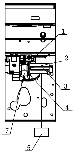
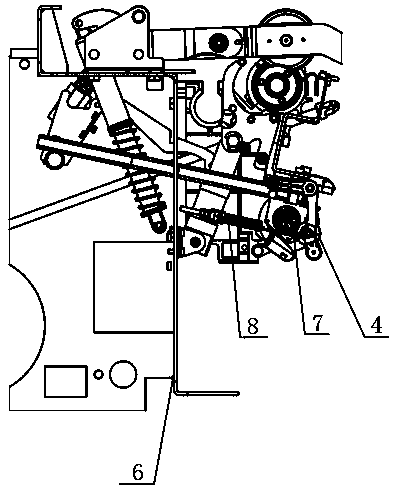
[0012] Such as Figure 1-2 A single-spindle yarn-leading mechani...


PUM


Abstract

The invention relates to a single-spindle yarn guide mechanism of a rotor spinning machine. Each spindle has a set of the single-spindle yarn guide mechanism. The single-spindle yarn guide mechanism comprises a yarn guide motor base, a spacer bush, a yarn guide motor, a yarn guide roller, an electric control box, a main beam and a leather roller; the yarn guide motor base is fixedly arranged on the main beam; the yarn guide motor is arranged on the yarn guide motor base; the yarn guide roller is connected with the yarn guide motor; the spacer bush is arranged between the yarn guide motor and the yarn guide roller; the electric control box and the yarn guide motor are connected and in driving control; the yarn guide roller is contacted with the leather roller; one end of a spring is arranged on the leather roller; and the leather roller is contacted with the yarn guide roller through a spring. According to the single-spindle yarn guide mechanism of rotor spinning machine in the invention, each spindle has a set of the single-spindle yarn guide mechanism; installation and debugging are convenient; because of single-spindle transmission, the load of the motor is small; the running precision of the motor is high; back and forward rotation angles of the yarn guide roller can be precisely controlled; therefore, the back and forward rotation length of yarns can be precisely controlled; and the precision and the reliability of yarn guiding, splicing, collective tailing and collective starting actions can be improved.

Description

technical field [0001] The invention belongs to the technical field of rotor spinning machines, and in particular relates to a yarn guiding mechanism for a single spindle of a rotor spinning machine. Background technique [0002] When the semi-automatic rotor spinning machine is spinning, the yarn delivery roller, which is composed of the yarn delivery roller and the yarn delivery rod touching each other, clamps and pulls the condensed and twisted yarn in the rotor out of the spinner, and then the winding roller The yarn bobbin is driven to clamp the winding yarn, and the yarn delivery roller is driven by the yarn delivery rod which is always in a rotating state to drive the yarn delivery cot to rotate simultaneously to clamp and draw the yarn. When yarn breakage occurs, the yarn will be detached from the yarn delivery roller after being continuously wound. The single-spindle yarn guiding mechanism of the existing rotor spinning machine adopts the single-side whole vehicle ...

Claims


Application Information

Patent Timeline
IPC IPC(8): D01H1/38
CPCD01H1/38
Inventor 雷晓民张跃峰王开杰苏伟韩芳刘恒贾学林杜康
Owner JINGWEI INTELLIGENT TEXTILE MACHINERY CO LTD
Features
  • R&D
  • Intellectual Property
  • Life Sciences
  • Materials
  • Tech Scout
  • Unparalleled Data Quality
  • Higher Quality Content
  • 60% Fewer Hallucinations
Learn More