Eureka AIR delivers breakthrough ideas for toughest innovation challenges, trusted by R&D personnel around the world.

Bleaching and dyeing device for textile machinery

A textile machinery, bleaching and dyeing technology, applied in the processing of textile material equipment configuration, textile and papermaking, and textile material processing, etc., can solve the problems of deteriorating textile quality, insufficient textile bleaching and dyeing, and textile de-dyeing. effect of probability

Inactive Publication Date: 2020-04-10
赵婷
View PDF0 Cites 2 Cited by
  • Summary
  • Abstract
  • Description
  • Claims
  • Application Information

AI Technical Summary

Problems solved by technology

[0003] Existing textile bleaching and dyeing devices are not deep enough for textile bleaching and dyeing, and the surface of textiles may be de-dyed, resulting in a decline in the quality of textiles, and the selling price cannot be increased.

Method used


Image

  • Bleaching and dyeing device for textile machinery
  • Bleaching and dyeing device for textile machinery
  • Bleaching and dyeing device for textile machinery

Examples


Embodiment 1

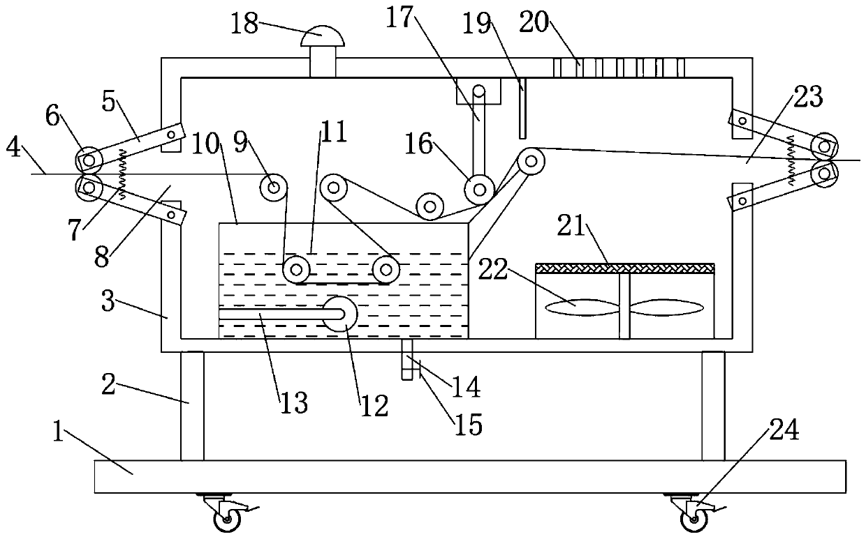
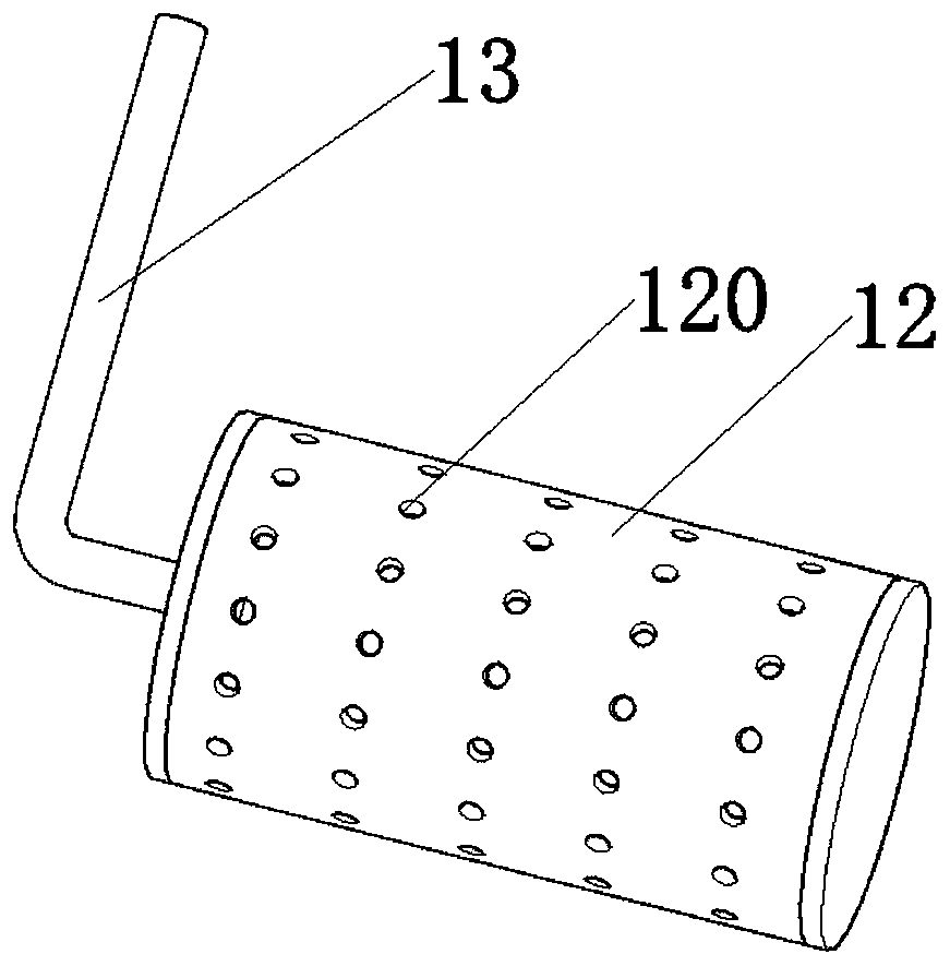
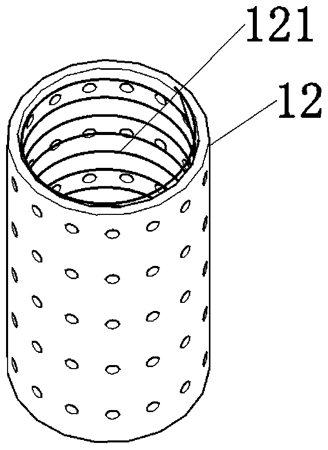
[0024] combine Figure 1-3 As shown, a bleaching and dyeing device for textile machinery includes a base 1, a column 2 is arranged on the base 1, a housing 3 is installed on the column 2, and a material inlet 8 and an outlet are provided on the housing 3. The feed port 23, the housing 3 at the position of the feed port 8 and the discharge port 23 are symmetrically provided with a clamping cylinder 6, and a spring 7 is arranged between the clamping cylinders 6, and the textile body 4 passes through The clamping cylinder 6 and the feeding port 8 enter the interior of the housing 3, and the textile body 4 enters the bleaching and dyeing tank 10 through the tensioning cylinder 9 inside the housing 3, and the bleaching and dyeing tank 10 is provided with a bubbling cylinder 12, Small holes 120 for air outlet are evenly distributed on the bubble tube 12, a first heating wire 121 is arranged inside the bubble tube 12, and the bubble tube 12 is connected with the air inlet pipe 13 pas...

Embodiment 2

[0037] This embodiment is a further improvement and limitation of embodiment 1 on the basis of embodiment 1.

[0038] A kind of bleaching and dyeing device for textile machinery, comprising all parts in embodiment 1, also includes:

[0039] Further, the right side of the bleaching and dyeing tank 10 is provided with a dehydration device, the dehydration device includes a suspender 17, and the suspender 17 is rotatably connected to the connecting block provided on the top of the housing 3, and the suspender 17 is rotatably connected to There is an extrusion cylinder 16, and a slope is provided on the right side of the bleaching and dyeing pool 10, and the suspension rod 17 is placed on the slope in combination with the extrusion cylinder 16.

[0040] Specifically, the dehydration device includes a squeeze cylinder 16. The squeeze cylinder 16 is placed on a slope. When the textile body 4 moves to the right, the squeeze cylinder 16 is closely attached to the textile body 4 to ach...


PUM


Abstract

The invention discloses a bleaching and dyeing device for textile machinery, relates to the technical field of textile processing, and mainly solves the problem that the textile quality is reduced dueto the fact that an existing textile bleaching and dyeing device easily causes destaining. The device comprises a base; a stand column is arranged on the base; a shell is mounted on the stand column;the shell is provided with a feeding hole and a discharging hole; clamping cylinders are arranged at the positions of the feeding hole and the discharging hole; a woven fabric body enters the interior of the shell through the clamping cylinders; the woven fabric body enters a bleaching and dyeing pool through a tensioning cylinder in the shell; a bubbling cylinder is arranged in the bleaching anddyeing pool; a first electric heating wire is arranged in the bubbling cylinder; a slope is arranged on the right side of the bleaching and dyeing pool; a hanging rod is arranged at the top of the shell; an extrusion cylinder is rotationally connected to the hanging rod; and a dewatering device and a drying device are arranged on the right side of the bleaching and dyeing pool. High-quality bleaching and dyeing of a woven fabric are achieved through the tensioning cylinder, the bleaching and dyeing pool, the bubbling cylinder and the first electric heating wire.

Description

technical field [0001] The invention relates to the technical field of textiles, in particular to a bleaching and dyeing device for textile machinery. Background technique [0002] Textiles generally need to be bleached and dyed after production, so as to deepen the color and brightness of the textiles and improve the ornamental degree of the textiles. [0003] Existing textile bleaching and dyeing devices are not deep enough for textile bleaching and dyeing, and the surface of textiles may be decolorized, resulting in a decline in the quality of textiles, and the selling price cannot be increased. Contents of the invention [0004] The purpose of the embodiments of the present invention is to provide a bleaching and dyeing device for textile machinery to solve the problems raised in the above-mentioned background technology. [0005] In order to achieve the above purpose, embodiments of the present invention provide the following technical solutions: [0006] A bleachin...

Claims


Application Information

Patent Timeline
IPC IPC(8): D06B3/20D06B15/02D06B15/00D06B23/20
CPCD06B3/20D06B15/00D06B15/02D06B23/20D06B2700/36
Inventor 赵婷
Owner 赵婷
Why Eureka
Eureka Blog
Learn More