A construction method for pouring concrete through the back of the steel pipe

A construction method and concrete technology, which is applied in the fields of earthwork drilling, construction, and infrastructure engineering, etc., can solve the problems of reduced concrete height, low strength, and increased cost, and achieve the effects of strengthening control, facilitating pouring, and reducing the amount of grouting

Active Publication Date: 2021-04-06
北京京水建设集团有限公司
View PDF7 Cites 0 Cited by
  • Summary
  • Abstract
  • Description
  • Claims
  • Application Information

AI Technical Summary

Problems solved by technology

[0005] The above scheme has the following disadvantages: when pouring one ash pouring port and pouring the next ash pouring port, the concrete at the poured ash pouring port will flow to the area that has not yet been poured, so that the poured ash pouring port will The height of the concrete at the place is reduced; after the pouring is completed, there is a large void layer on the top of the backfilled concrete, which requires a lot of grouting treatment, resulting in increased costs, and the strength of the backfilled grout at the top of the annular layer is low after solidification

Method used


Image

  • A construction method for pouring concrete through the back of the steel pipe
  • A construction method for pouring concrete through the back of the steel pipe
  • A construction method for pouring concrete through the back of the steel pipe

Examples


Embodiment

[0045] Embodiment: A construction method for pouring concrete behind the hole through the steel pipe 2, comprising the following construction steps:

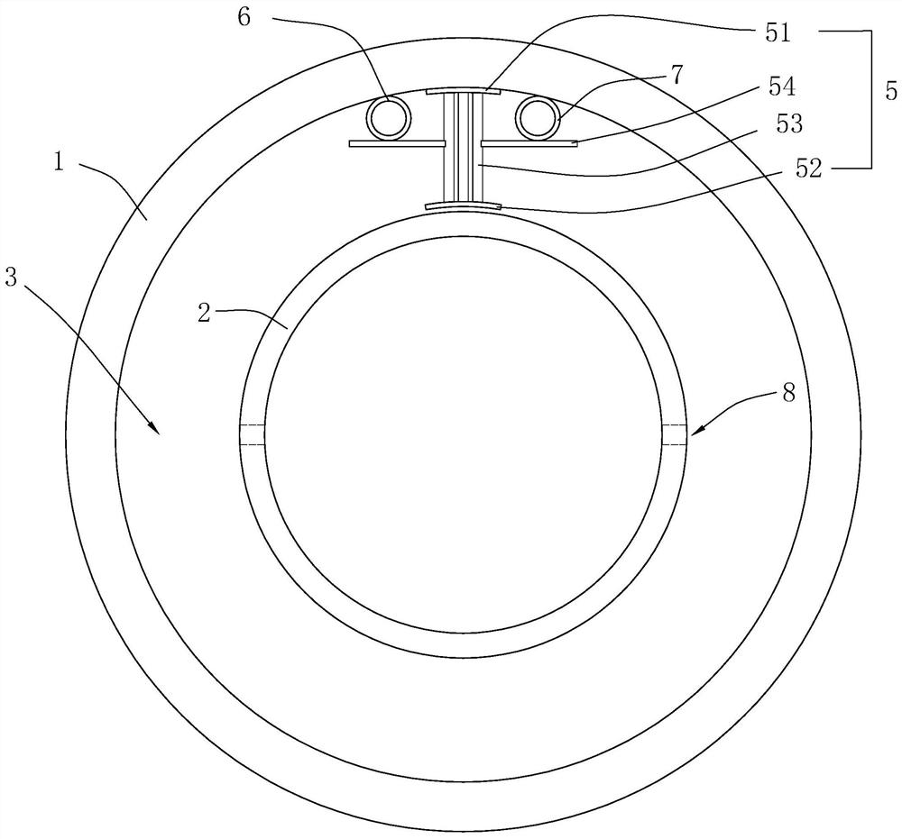
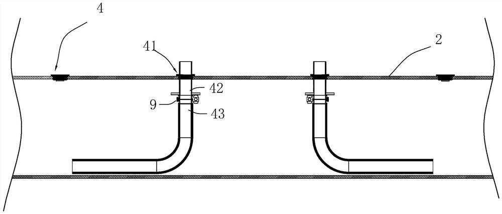
[0046] Step 1. Preparation: refer to figure 2 and image 3 Install the exhaust pipe 7 and the grouting pipe 6 on the top of the annular space layer 3 that penetrates the steel pipe 2 and the concrete pipe 1, the exhaust pipe 7 and the grouting pipe 6 are arranged in length, and the two ends pass through the ends of the steel pipe 2 ; The annular space layer 3 at both ends of the steel pipe 2 is blocked by building a wall. A plurality of ash filling ports 4 are provided at intervals on the top of the pierced steel pipe 2, and the distance is 3 meters. Two sets of ground pump systems are installed at both ends of the steel pipe 2 through the hole, and two pouring pipes 43 are respectively installed from the two ports of the steel pipe 2 through the hole to the middle position.

[0047] Step 2, pouring the first-stage concrete ...


PUM


Abstract

The invention discloses a construction method for pouring concrete through the back of a steel pipe. The technical scheme includes preparation work, pouring of the first-stage concrete, pouring of the second-stage concrete, grouting construction and anti-corrosion treatment. Install exhaust pipes and grouting pipes on the top of the annular layer that penetrates the steel pipe and concrete pipe, and build walls at both ends of the annular layer to seal. A plurality of ash filling ports are opened at the top of the pierced steel pipe. The pouring pipe is connected with the ash pouring port, and the first stage concrete is poured; when the height of the concrete is close to the middle height of the pierced steel pipe, the pouring pipe is moved to the next ash pouring port, and the pouring steps are repeated. Install the pouring pipe again and start pouring the second stage concrete. When the next ash pouring port is evenly and stably leaking grout, stop pouring, the pouring pipe moves to the next ash pouring port, and the pouring ash pouring port is permanently blocked. Inject grout into the grouting pipe to fill the top cavity. Carry out anti-corrosion treatment on the ash filling port. The invention has the advantages of making poured self-tight concrete more plump and reducing the amount of grouting.

Description

technical field [0001] The invention relates to the technical field of tunnel-piercing construction technology, in particular to a construction method for pouring concrete behind a tunnel-piercing steel pipe. Background technique [0002] Water conveyance tunnel is an important part of water diversion and diversion projects. At present, multi-layer lining is often used. Generally speaking, it includes: outer-lined concrete pipe, inner-lined hole-piercing steel pipe and filling between the outer lining and inner lining. Self-compacting concrete in the annular layer, etc. [0003] Referring to the Chinese patent with the patent application number CN201811628435.5, the current scheme of backfilling concrete in the annulus includes a tunnel body and a steel pipe installed in the tunnel body, an interlayer is left between the tunnel body and the steel pipe, and the The two ends of the interlayer are closed, and an exhaust port is reserved. A pouring pipe is arranged at intervals...

Claims


Application Information

Patent Timeline
Patent Type & Authority Patents(China)
IPC IPC(8): E21D11/10
CPCE02D15/00
Inventor 杜芊杨栗程大伟卫耀宗赵小山
Owner 北京京水建设集团有限公司
Why Eureka
Try Eureka