Well cementation process suitable for gas field
A cementing and process technology, used in wellbore/well components, drilling compositions, products, etc., can solve the problems of the overall pressure bearing capacity and sealing performance, and achieve low cost, good rheological performance, and low cost. The effect of density
- Summary
- Abstract
- Description
- Claims
- Application Information
AI Technical Summary
Problems solved by technology
Method used
Image
Examples
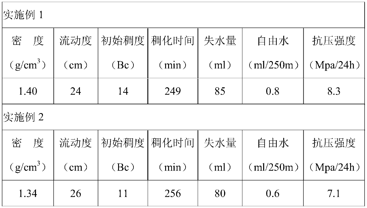
Embodiment 1
[0037] Step 1. Inject drilling fluid into the well for a pressure test, and if leakage occurs in the well, plug the leaking formation;
[0038] Step 2. Lower multiple casings to the bottom of the well one by one, add centralizers into the well to ensure that the casings are centered, and inject mud between the well wall and the casing every time 20 casings are run, and ensure that the drilling fluid is circulated for at least two times in the middle. Second, adjust the performance of the drilling fluid after running the casing to ensure that the bottom of the well is clean and free of sand;
[0039] Step 3. Inject pre-fluid, first cementing fluid, and second cementing fluid into the casing in sequence, and then release the rubber plug, and use the rubber plug to scrape off the first cementing fluid and the second cementing fluid on the inner wall of the casing ;
[0040] The first cementing fluid includes the following components according to the mass fraction: Three Gorges G...
Embodiment 2
[0043] Step 1. Inject drilling fluid into the well for a pressure test, and if leakage occurs in the well, plug the leaking formation;
[0044] Step 2. Lower multiple casings to the bottom of the well one by one, add centralizers into the well to ensure that the casings are centered, and inject mud between the well wall and the casing every time 22 casings are run, and ensure that the drilling fluid is circulated for at least two times in the middle. Second, adjust the performance of the drilling fluid after running the casing to ensure that the bottom of the well is clean and free of sand;
[0045] Step 3. Inject pre-fluid, first cementing fluid, and second cementing fluid into the casing in sequence, and then release the rubber plug, and use the rubber plug to scrape off the first cementing fluid and the second cementing fluid on the inner wall of the casing ;
[0046] The first cementing fluid includes the following components according to the mass fraction: Three Gorges G g...
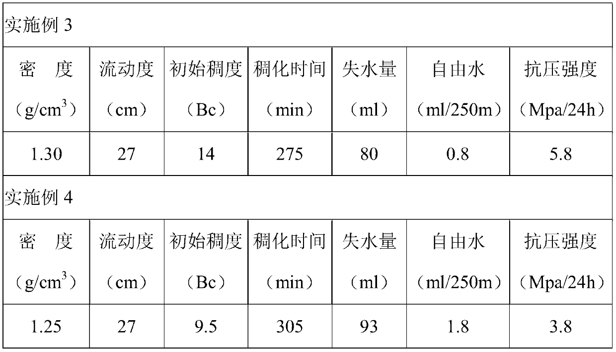
Embodiment 3
[0049] Step 1. Inject drilling fluid into the well for a pressure test, and if leakage occurs in the well, plug the leaking formation;
[0050] Step 2. Lower multiple casings to the bottom of the well one by one, add centralizers into the well to ensure that the casings are centered, and inject mud between the well wall and the casing every time 25 casings are run, and ensure that the drilling fluid is circulated for at least two times in the middle. Second, adjust the performance of the drilling fluid after running the casing to ensure that the bottom of the well is clean and free of sand;
[0051] Step 3. Inject pre-fluid, first cementing fluid, and second cementing fluid into the casing in sequence, and then release the rubber plug, and use the rubber plug to scrape off the first cementing fluid and the second cementing fluid on the inner wall of the casing ;
[0052] The first cementing fluid includes the following components according to the mass fraction: Three Gorges G...
PUM
 Abstract
Description
Claims
Application Information
 - R&D
- Intellectual Property
- Life Sciences
- Materials
- Tech Scout
- Unparalleled Data Quality
- Higher Quality Content
- 60% Fewer Hallucinations
Browse by: Latest US Patents, China's latest patents, Technical Efficacy Thesaurus, Application Domain, Technology Topic, Popular Technical Reports.
© 2025 PatSnap. All rights reserved.Legal|Privacy policy|Modern Slavery Act Transparency Statement|Sitemap|About US| Contact US: help@patsnap.com


