Cutting and grinding pump

A technology for cutting discs and pump bodies, applied to pumps, pump components, non-variable pumps, etc., can solve problems such as poor cutting effect, low tool hardness, and large pump body inlet, so as to improve cutting effect and efficiency, improve Cutting effect, the effect of improving cutting efficiency

Inactive Publication Date: 2020-04-10
新界泵业(浙江)有限公司
View PDF0 Cites 1 Cited by
  • Summary
  • Abstract
  • Description
  • Claims
  • Application Information

AI Technical Summary

Problems solved by technology

[0002] There are various kinds of cutting pumps on the market, the quality is uneven, and there are various problems, which make it difficult to meet the growing tasks of urban sewage treatment and cutting transportation.
The existing cutting pump adopts a cast iron impeller and a spiral base to form a cutting mechanism. The inlet of the pump body is large, and the hardness of the tool is low, and the cutting effect is poor; But there are still problems: low efficiency, easy blockage of the pump body inlet, etc.

Method used


Image

  • Cutting and grinding pump
  • Cutting and grinding pump
  • Cutting and grinding pump

Examples


Embodiment

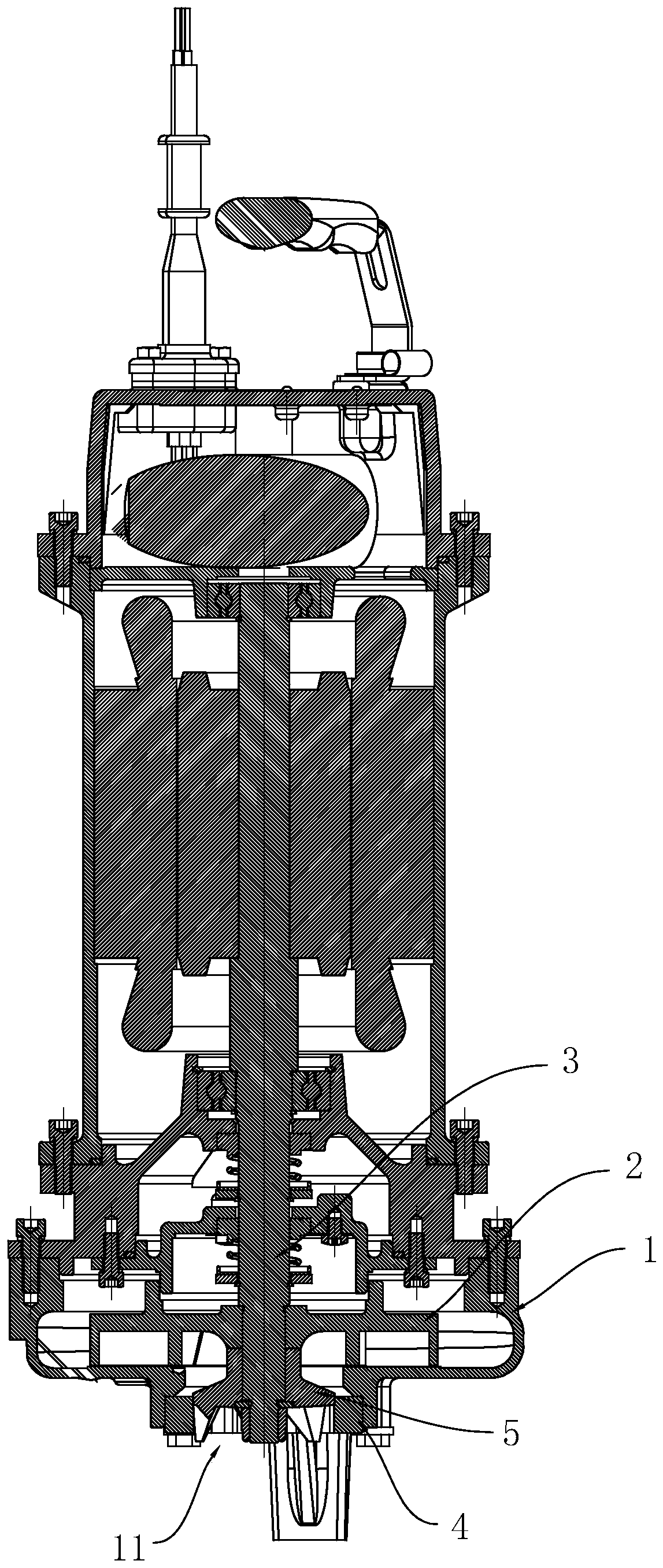
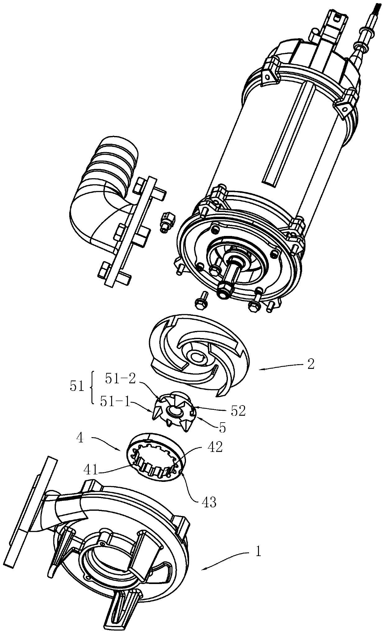
[0024] Example: such as Figure 1-10 As shown, the cutting and grinding pump includes a pump body 1 with a water inlet 11 and a water outlet, an impeller 2 matched with the flow passage of the pump body, and a pump shaft 3 that drives the impeller to rotate. The water inlet and outlet are connected to the flow passage. Cooperate.

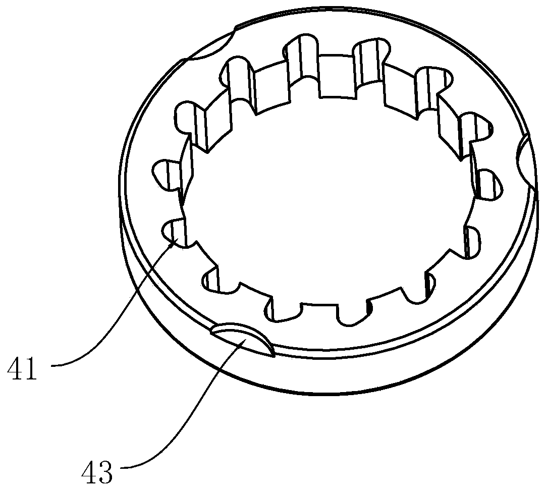
[0025] The cutting and grinding pump also includes a guide disc 4 matched with the water inlet 11 and a cutting disc 5 matched with the guide disc. The cutting disc 5 is arranged on the pump shaft 3. The guide disc 4 is in the shape of an annular disc, the inner ring wall of the guide disc is provided with a plurality of water inlet holes 41, the cutting disc is arranged in the inner cavity of the guide disc, and the edges of the cutting disc are evenly distributed A plurality of blade parts 51, the blade parts are matched with the inner ring wall 52 of the guide plate. A guide disc and a cutting disc are arranged at the water inlet of the pump body....


PUM


Abstract

The invention relates to a cutting and grinding pump. The cutting and grinding pump solves the problems existing in the prior art that the cutting effect is not very good and an impeller is prone to being stuck and the like. According to the adopted technical scheme, the cutting and grinding pump further includes a guide disk matched with a water inlet and a cutting disk matched with the guide disk, wherein the cutting disk is arranged on a pump shaft, and the guide disk is in the shape of an annular disk; a plurality of water inlet holes are formed in the inner ring wall of the guide disk, and the cutting disk is arranged in an inner cavity of the guide disk; and a plurality of blade parts are evenly distributed at the edge of the cutting disk, and the blade parts are matched with the inner ring wall of the guide disk. The cutting and grinding pump has the effects that the guide disk and the cutting disk are arranged at the water inlet of a pump body, the guide disk enables fluid to enter a flow path of the pump body through the water inlet holes, the guide disk and the cutting disk are matched to play a cutting effect and a filtering function to filter impurities, the effectiveness of cutting is improved, and the occurrence of blockage at the water inlet of the pump body is greatly reduced.

Description

Technical field [0001] The invention relates to a cutting and grinding pump, in particular to a cutting and grinding pump with an improved cutting structure. Background technique [0002] There are many kinds of cutting pumps on the market, the quality is uneven, there are various problems, it is difficult to meet the growing urban sewage treatment and cutting and transportation tasks. The existing cutting pump adopts a cast iron impeller and a spiral base to form a cutting mechanism. The pump body has a large inlet and the cutting tool has low hardness. The cutting effect is poor; or the impeller and cutting knife on the cutting pump are separate structures, although the cutting effect has been improved, However, there are still problems such as low efficiency and easy blockage of the pump inlet. Summary of the invention [0003] The purpose of the present invention is to solve the above-mentioned problems existing in the prior art and provide a cutting and grinding pump. A guid...

Claims


Application Information

Patent Timeline
Patent Type & Authority Applications(China)
IPC IPC(8): F04D7/04F04D29/44F04D29/00F04D29/70F04D29/42
CPCF04D7/045F04D29/007F04D29/4293F04D29/445F04D29/708
Inventor 李海尧应卓浪刘学敏
Owner 新界泵业(浙江)有限公司
Why Eureka
Try Eureka