A Centrifugal Spherical Roller Bearing

A self-aligning roller bearing and centrifugal technology, applied in the field of bearing mechanisms, can solve the problems of small self-aligning angle of the self-aligning roller bearing and the inability to adjust the rotating shaft, so as to reduce vibration and noise, improve the adjustment ability and prolong the service life. Effect

Active Publication Date: 2021-08-13
山东华工轴承有限公司
View PDF0 Cites 0 Cited by
  • Summary
  • Abstract
  • Description
  • Claims
  • Application Information

AI Technical Summary

Problems solved by technology

[0004] The invention provides a centrifugal self-aligning roller bearing, which has the advantages of large self-aligning angle, being applicable to rotating shafts with high rotating speed, low vibration and noise, and high stability, and solves the problem of existing self-aligning roller bearings. The center of rotation adjustment of the spherical roller bearing is realized by the rotation and oscillation of the inner ring, resulting in a small self-aligning angle of the spherical roller bearing, and it can only be applied to the working condition of low speed. At the same time, the existing The adjustment method of the self-aligning roller bearing rotation swing can only adjust the shaft on the same center line, but cannot adjust the shaft in the eccentric motion state

Method used


Image

  • A Centrifugal Spherical Roller Bearing
  • A Centrifugal Spherical Roller Bearing
  • A Centrifugal Spherical Roller Bearing

Examples


Embodiment Construction

[0021] The following will clearly and completely describe the technical solutions in the embodiments of the present invention with reference to the accompanying drawings in the embodiments of the present invention. Obviously, the described embodiments are only some, not all, embodiments of the present invention. Based on the embodiments of the present invention, all other embodiments obtained by persons of ordinary skill in the art without making creative efforts belong to the protection scope of the present invention.

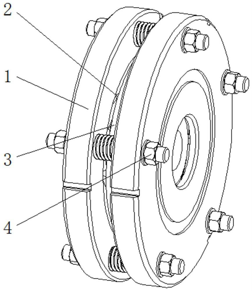
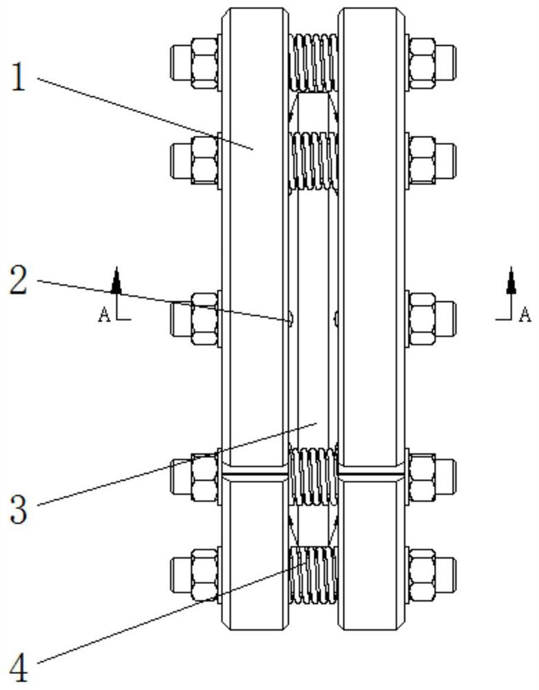
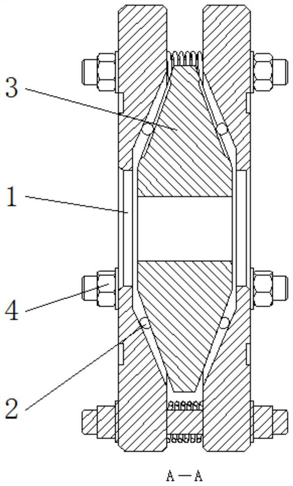
[0022] see Figure 1-6 , a centrifugal self-aligning roller bearing, including a bearing outer ring 1, a rotating roller 2, a bearing inner ring 3 and a tension pin 4, the bearing outer ring 1 is provided with two sets of left and right sets, and the left and right sets of bearing outer rings 1 They are fixedly connected by a tension pin 4, and the inner wall of the bearing outer ring 1 is rollingly connected with the chute on the outer surface of the bearing ...


PUM


Abstract

The invention relates to the technical field of bearing mechanisms, and discloses a centrifugal self-aligning roller bearing, which includes a bearing outer ring. The bearing outer ring is provided with two groups of left and right. The inner wall of the bearing outer ring passes through the rotating roller and the bearing. The sliding grooves on the outer surface of the inner ring are connected by rolling. The centrifugal self-aligning roller bearing, through the arrangement of the outer ring of the bearing, the rotating roller and the inner ring of the bearing, uses the centrifugal force generated by the inner ring of the bearing when it rotates with the rotating shaft at high speed to drive the rotating roller along the inner ring of the bearing. The chute moves outward, so that the rotating rollers can always provide sufficient support for the inner ring of the bearing, and when the shaft moves eccentrically due to installation errors or bending, the inner ring of the bearing can be moved between the two sets of rotating rollers It rotates with a large radius of rotation without excessive wear, which effectively prolongs the service life of the roller bearing, and at the same time reduces the vibration and noise generated by the roller bearing during operation.

Description

technical field [0001] The invention relates to the technical field of bearing mechanisms, in particular to a centrifugal spherical roller bearing. Background technique [0002] Spherical roller bearing is a kind of inner ring with two raceways and inclined at an angle relative to the bearing axis, while the outer ring has a common spherical raceway, so it is not easy to be affected by the installation error of the rotating shaft or the rotating shaft when the inner ring rotates. The eccentric movement caused by the rao's bending has its own bearings to adjust the center of rotation. However, the existing spherical roller bearings adjust the center of rotation through the rotation and swing of the inner ring, resulting in the self-aligning The self-aligning angle of the roller bearing is small, and it can only be applied to the working condition of low speed. At the same time, the existing adjustment method for the rotation and oscillation of the self-aligning roller bearing...

Claims


Application Information

Patent Timeline
Patent Type & Authority Patents(China)
IPC IPC(8): F16C23/08F16C27/04F16C33/58
CPCF16C23/08F16C27/04F16C33/583F16C2300/22
Inventor 贾方益
Owner 山东华工轴承有限公司
Why Eureka
Try Eureka