
Petrochemical engineering delivery pipeline

A technology for conveying pipelines and petrochemicals. It is used in pipeline protection, pipeline anti-corrosion/rust protection, pipeline damage/wear prevention, etc. It can solve the problem of long underwater operation time, loose flange connections, and high maintenance and maintenance costs for submarine pipelines. and other problems to achieve the effect of improving connection efficiency, increasing service life, and reducing maintenance and maintenance cycles.

Active Publication Date: 2020-04-10
东营威联化学有限公司
View PDF9 Cites 1 Cited by
  • Summary
  • Abstract
  • Description
  • Claims
  • Application Information

AI Technical Summary

Problems solved by technology

[0003] The exploitation of offshore oil requires the laying of oil pipelines on the seabed for oil transportation. Unlike land, submarine oil pipelines need to withstand huge water pressure and various conditions brought about by harsh environments. At present, in offshore oil exploitation, The annual repair and maintenance costs for submarine pipelines are huge, and when the pipelines are connected, the underwater operation time is too long, so it is necessary to design an oil transportation pipeline with strong pressure resistance, which can adapt to the harsh environment of the seabed and is easy to connect, and can be used for a long time Sometimes, due to special reasons such as artificial maintenance and installation of oil pipelines, or natural disasters, the flange connection is easy to be loosened due to external impact, and then the oil transportation works normally. Therefore, a petrochemical pipeline is proposed to solve the above problems

Method used


Image

  • Petrochemical engineering delivery pipeline
  • Petrochemical engineering delivery pipeline
  • Petrochemical engineering delivery pipeline

Examples


Embodiment Construction

[0027] In order to make the technical means, creative features, goals and effects achieved by the present invention easy to understand, the present invention will be further described below in conjunction with specific embodiments.

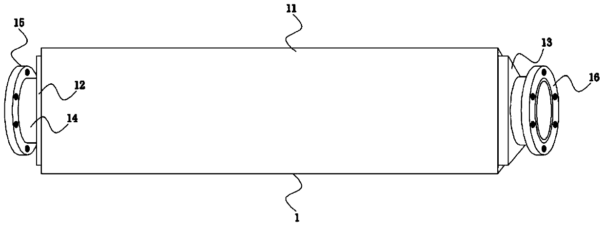
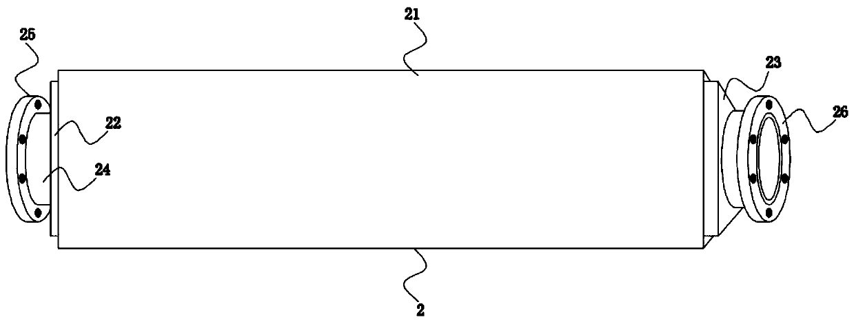
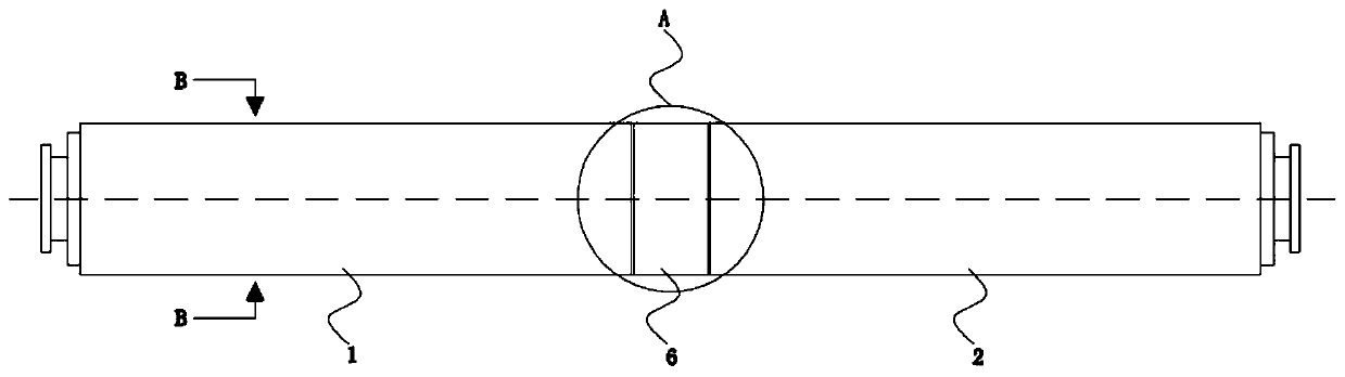
[0028] like Figure 1-Figure 7 As shown, a petrochemical transportation pipeline according to the present invention includes a first unit pipe 1 and a second unit pipe 2, and the first unit pipe 1 and the second unit pipe 2 are respectively provided with a first triangular protection The shell 11 and the second triangular protective shell 21, the left and right sides of the first unit tube 1 are fixedly connected with a first port tube 14, and the side of the first port tube 14 close to the second unit tube 2 is fixedly connected with a The first right flange 16, the side of the first port pipe 14 away from the second unit pipe 2 is fixedly connected with the first left flange 15, and the left and right sides of the second unit pipe 2 are fixedly ...


PUM


Abstract

The invention relates to the field of petroleum transportation, in particular to a petrochemical engineering delivery pipeline. The petrochemical engineering delivery pipeline comprises a first unit pipe and a second unit pipe. A first triangular protective shell and a second triangular protective shell are arranged outside the first unit pipe and the second unit pipe correspondingly. First port pipes are fixedly connected with the left and right sides of the first unit pipe correspondingly. The side, close to the second unit pipe, of one first port pipe is fixedly connected with a first rightflange, and the side, far away from the second unit pipe, of the other first port pipe is fixedly connected with a first left flange. Second port pipes are fixedly connected with the left and right sides of the second unit pipe correspondingly. The side, close to the first unit pipe, of one second port pipe is fixedly connected with a second left flange, and the side, far away from the first unitpipe, of the other second port pipe is fixedly connected with a second right flange. The first unit pipe and the second unit pipe are connected through the first right flange, the second left flangeand fixing bolts.

Description

technical field [0001] The invention relates to the field of petroleum transportation, in particular to a petrochemical transportation pipeline. Background technique [0002] Petroleum is one of the main objects of geological exploration. It is a viscous, dark brown liquid known as "industrial blood". There are oil reserves in some areas of the upper crust; the main components are various alkanes, naphthenes, and aromatic hydrocarbons The oil-forming mechanism of petroleum has two theories of biosedimentary oil and petrochemical oil. The former is more widely accepted. It is believed that oil is formed by organisms in ancient oceans or lakes after a long evolution. It belongs to biosedimentary oil and is non-renewable. The latter believes that oil is produced by the carbon in the earth's crust itself, which has nothing to do with biology and is renewable; the properties of oil vary according to the place of origin, the density is 0.8-1.0g / cm3, the viscosity range is very wid...

Claims


Application Information

Patent Timeline
IPC IPC(8): F16L23/026F16L58/00F16L57/00F16F15/067
CPCF16F15/067F16L23/026F16L57/00F16L58/00
Inventor 王俊玉刘振夏孝清郑豪
Owner 东营威联化学有限公司
Features
  • Generate Ideas
  • Intellectual Property
  • Life Sciences
  • Materials
  • Tech Scout
  • Unparalleled Data Quality
  • Higher Quality Content
  • 60% Fewer Hallucinations
Learn More