
Light source conversion wavelength switching device with rotary thumb wheel structure

A technology for switching devices and converting wavelengths, applied in measurement devices, material analysis by optical means, instruments, etc., can solve the problems of troublesome detection of different substances, incomplete detection of substances, low detection efficiency, etc., and achieves low production cost and structure. Compact and reasonable, the effect of improving detection efficiency

Inactive Publication Date: 2020-04-10
山东恒美电子科技有限公司
View PDF0 Cites 0 Cited by
  • Summary
  • Abstract
  • Description
  • Claims
  • Application Information

AI Technical Summary

Problems solved by technology

[0003] The working principle of the light wave detection instrument in the prior art is to irradiate the detection reagent with a light wave of a specific wavelength emitted by the light wave generator, and the substances in the detection reagent produce different changes for different wavelengths, and the wavelength change is received by the wavelength receiver. , and through a certain comparison and algorithm, the content of the substance is calculated; however, the light wave detection instruments in the prior art all use fixed wavelengths, that is to say, they can only detect a fixed substance, and each time a substance is detected, it is necessary to Replacing a device with a different wavelength will make the detection of substances incomplete, and it will be troublesome when different substances need to be detected, resulting in low detection efficiency
[0004] In summary, the existing technology obviously has inconvenience and defects in actual use, so it is necessary to develop a new type of light source conversion wavelength switching device to solve the problems existing in the prior art

Method used


Image

  • Light source conversion wavelength switching device with rotary thumb wheel structure
  • Light source conversion wavelength switching device with rotary thumb wheel structure
  • Light source conversion wavelength switching device with rotary thumb wheel structure

Examples


Embodiment 1

[0031] Embodiment 1 Rotary dial structure light source conversion wavelength switching device

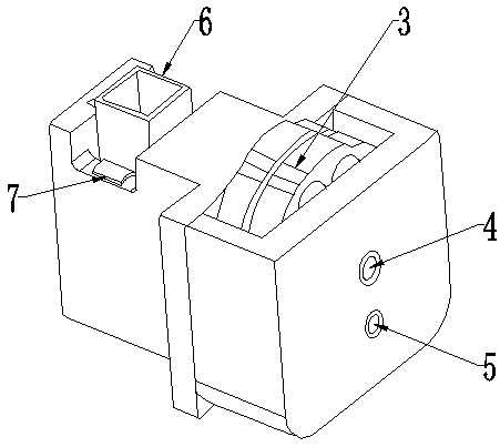
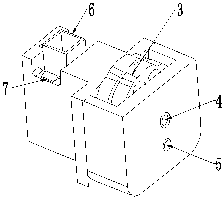
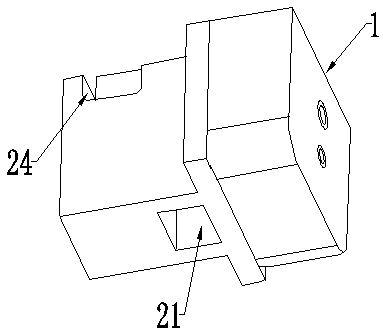
[0032] like Figure 1-Figure 6 Commonly shown, the present invention provides a rotary dial structure light source conversion wavelength switching device, including a transmitting block 1 and a receiving block 2, the ends of the transmitting block 1 and receiving block 2 are fixedly connected, and the connection method can be screw connection or glue Connect; the side of the transmitting block 1 close to the receiving block 2 is provided with a dial mounting hole 11, and the main body of the transmitting block 1 away from the receiving block 2 is provided with a through light source mounting hole 13 and a rotating shaft mounting hole 12, the rotating shaft The mounting hole 12 is located directly above the light source mounting hole 13; the light source mounting hole 13 is provided with a light wave generator 5; the rotating shaft mounting hole 12 is pierced with a horizontally arra...


PUM


Abstract

The invention discloses a light source wavelength conversion switching device with a rotary thumb wheel structure. The device comprises a transmitting block and a receiving block, a poking wheel is mounted in the transmitting block; a limiting device is arranged below the poking wheel; the end parts of the transmitting block and the receiving block are fixedly connected; a poking wheel mounting hole is formed in the side, close to the receiving block, of the transmitting block, a light source mounting hole and a rotating shaft mounting hole which are through are formed in the main body on theside, away from the receiving block, of the transmitting block, the rotating shaft mounting hole is located over the light source mounting hole, a rotating shaft penetrates through the rotating shaftmounting hole, and two poking wheels of the same structure are mounted on the main body of the rotating shaft. Light rays with different wavelengths can be rapidly switched, so that detection of different items is carried out, and the detection efficiency of a detection instrument is improved; the wavelength switching device is compact and reasonable in structure and low in manufacturing cost.

Description

technical field [0001] The invention relates to a wavelength switching device, in particular to a rotary dial structure light source conversion wavelength switching device, which belongs to the technical field of detection instruments. Background technique [0002] At present, light wave detection instruments are widely used in soil detection, food detection, pesticide residue detection and other fields. [0003] The working principle of the light wave detection instrument in the prior art is to irradiate the detection reagent with a light wave of a specific wavelength emitted by the light wave generator, and the substances in the detection reagent produce different changes for different wavelengths, and the wavelength change is received by the wavelength receiver. , and through a certain comparison and algorithm, the content of the substance is calculated; however, the light wave detection instruments in the prior art all use a fixed wavelength, that is to say, they can onl...

Claims


Application Information

Patent Timeline
Patent Type & Authority Applications(China)
IPC IPC(8): G01N21/01
CPCG01N21/01G01N2021/015
Inventor 王永恒
Owner 山东恒美电子科技有限公司
Learn More