
Current detection circuit and current detection method

A current detection circuit and current detection technology, applied in the direction of measuring current/voltage, only measuring current, measuring devices, etc., can solve the problem of too fast, a large amount of current flows through the dark current path, and the current supply time cannot provide enough current. To solve problems such as electrical protection, achieve simple and effective control methods, and reduce the risk of incorrect measurement or measurement component burnout

Inactive Publication Date: 2020-04-10
QISDA OPTRONICS (SUZHOU) CO LTD +1
View PDF8 Cites 1 Cited by
  • Summary
  • Abstract
  • Description
  • Claims
  • Application Information

AI Technical Summary

Problems solved by technology

The main reason is that the path of the working current (working current) when detecting a large current must be different from the path of the dark current (dark current) when detecting a small current. The resistance value used to measure the large current on the working current path is generally lower Relatively small (such as micro or milliohm level), and the resistance value used to measure small currents on the dark current path is generally relatively large (such as milli-ohm level or greater), otherwise the smaller current goes through the working current path The corresponding current detection amplifier will not be able to measure the current value, and if the large current goes through the dark current path, the corresponding current detection amplifier will have the risk of overheating and burning the components due to the large voltage difference
[0004] Furthermore, when the load in the circuit changes, its current magnitude will change according to the demand of the load, so it is very easy to cause the risk of the above-mentioned current measurement not being measured or the current detection amplifier component being overheated and burned. Therefore, some current circuits The design will add a control signal to the switch to switch
However, during the switching process, the following risks may arise due to the time difference: (1) If the switching response is too slow when the small current is cut into a large current, and a large amount of current flows through the dark current path, the corresponding current detection amplifier will have The risk of component overheating and burning; (2) If the switch reacts too quickly when switching from high current to small current, and a large amount of current flows through the dark current path, the corresponding current detection amplifier has the risk of component overheating and burning; (3) if the switch The response is too fast, and the current supply time difference caused by the resistance used to measure the large current on the working current path or the resistance used to measure the small current on the dark current path may not be able to provide enough current in an instant, and the load will be interrupted due to an instant. The power supply cannot continue to perform operations, and there are phenomena such as restart or power failure protection.
[0005] In addition, when measuring small currents, because the relevant circuits of the current sense amplifier on the working current path are still mounted on the load, there is a risk of current back-feeding into the current sense amplifier, which easily leads to inaccurate measurement (other leakage caused by components), and vice versa
If a switch is added in front of the load, the above-mentioned risk of being unable to continue operation due to momentary power failure is even higher, and it also increases the overall cost

Method used


Image

  • Current detection circuit and current detection method

Examples


Embodiment Construction

[0022] In order to have a further understanding of the purpose, structure, features, and functions of the present invention, the following detailed descriptions are provided in conjunction with the embodiments.

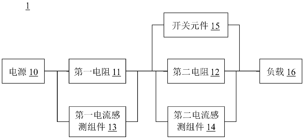
[0023] See figure 1 , figure 1 It is a schematic diagram of a current detection circuit according to an embodiment of the present invention. The current detection circuit 1 of the present invention is used to selectively measure a first current or a second current, and the current value of the first current is greater than the current value of the second current.

[0024] The current detection circuit 1 includes a power source 10 , a first resistor 11 , a second resistor 12 , a first current sensing component 13 , a second current sensing component 14 , a switching element 15 and a load 16 .

[0025] The first resistor 11 and the second resistor 12 are electrically connected in series between the power source 10 and the load 16 .

[0026] The first current sensing ...


PUM


Abstract

The invention provides a safe and efficient current detection circuit and a current detection method. The current detection circuit comprises a power supply, a first resistor, a second resistor, a first current sensing assembly, a second current sensing assembly, a switch element and a load. The first resistor and the second resistor are electrically connected in series between a power supply anda load. The first current sensing assembly is coupled to the first resistor, and the second current sensing assembly is coupled to the second resistor. The switching element is connected in parallel to two ends of the second resistor; the resistance value of the first resistor is smaller than that of the second resistor; in a state of measuring the first current, the switch element is closed and conducted, the current from the power supply to the load flows through the first resistor and the switch element, and the first current sensing assembly measures the first current flowing through the first resistor; in the state of measuring the second current, the switch element is open-circuited and switched off, the current from the power supply to the load flows through the first resistor and the second resistor, and the second current sensing assembly measures the second current flowing through the second resistor.

Description

technical field [0001] The invention relates to an electrical detection circuit, in particular to a current detection circuit and a current detection method. Background technique [0002] Current detection circuits are often used in current detection scenarios such as high-voltage short-circuit protection, motor control, DC / DC converters, system power management, secondary battery current management, and battery management. When a general electronic electromechanical product needs to measure current, a current detection element, such as a current-sense amplifier (current-sense amplifier), is added to the current flow path to monitor the current consumed by the electronic electromechanical product. [0003] When the electronic and electromechanical products to be monitored need to monitor two or more currents, a switch, such as a load switch or relay, is needed to switch the current changes under different usage conditions. The main reason is that the path of the working cur...

Claims


Application Information

Patent Timeline
Patent Type & Authority Applications(China)
IPC IPC(8): G01R19/00G01R15/00
CPCG01R19/0092G01R15/002
Inventor 游朝顺
Owner QISDA OPTRONICS (SUZHOU) CO LTD
Learn More