Frequency measurement device applied to inertial navigation system and frequency measurement method thereof

An inertial navigation system and frequency measurement technology, applied in the field of frequency measurement, can solve problems such as inconvenient timing, and achieve the effects of simple use, reduced timing requirements, and improved reliability

Active Publication Date: 2020-04-10
BEIJING AUTOMATION CONTROL EQUIP INST
View PDF8 Cites 0 Cited by
  • Summary
  • Abstract
  • Description
  • Claims
  • Application Information

AI Technical Summary

Problems solved by technology

[0004] The above method starts from the rising edge of the gate to the moment when the first rising edge of the signal to be measured arrives, and latches the non-full cycle count; but in the actual continuous measurement engineering application, if there is a certain phase difference between the frequency input and the gate signal, like figure 1 As shown, the non-integral cycle time (Ti) latch moment of the signal to be tested depends on the period from the gate signal to the first rising edge of the signal to be tested, so that the processor can enter the interrupter to read the measured value, so, For application systems that require synchronous calculations for frequency measurement using vibrating beam accelerometers, it will cause inconvenience in timing

Method used


Image

  • Frequency measurement device applied to inertial navigation system and frequency measurement method thereof
  • Frequency measurement device applied to inertial navigation system and frequency measurement method thereof
  • Frequency measurement device applied to inertial navigation system and frequency measurement method thereof

Examples


Embodiment Construction

[0025]The present invention will be described in detail below in conjunction with the accompanying drawings and embodiments, but the protection scope of the present invention is not limited by the embodiments. In order to enhance the understanding of the present invention, specific details are set forth in the following preferred embodiments, but those skilled in the art can fully understand the present invention without the description of these details. The device models of the embodiments of the present invention are not subject to other restrictions unless otherwise specified, as long as the device can complete the corresponding function. In addition, well-known components, circuits, methods, etc. have not been described in detail in order to avoid unnecessary obscuring the essence of the present invention.

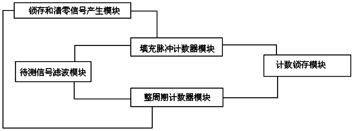
[0026] In one embodiment of the present invention, as figure 2 As shown, a frequency measuring device applied to an inertial navigation system of the present inventi...


PUM


Abstract

The invention relates to a frequency measurement device applied to an inertial navigation system and a frequency measurement method thereof. The device comprises a to-be-measured signal filtering module, a latch and zero clearing signal generation module, a full-period counter module, a filler pulse counter module and a counting latch module, wherein the to-be-measured signal filtering module performs filtering processing on a to-be-measured signal; the latch and zero clearing signal generation module generates a timing latch signal and a timing zero clearing signal; the full-period counter module counts the pulses of the to-be-measured signal in the whole cycle and sends the obtained value to the counting latch module; the filler pulse counter module is used for counting non-full-period filling high-frequency pulses before a sampling gate period starts and sending an obtained value to the counting latch module; and the counting latch module is used for receiving and storing the counting value sent by the full-period counter module, and is also used for receiving, processing and storing the count value sent by the filler pulse counter module. According to the invention, the problemthat the to-be-measured signal depends on the count value of a gate rear edge is solved, and the time sequence requirement on the gate rear edge is reduced.

Description

technical field [0001] The invention belongs to the technical field of frequency measurement, and relates to a frequency measurement device applied to an inertial navigation system and a frequency measurement method thereof. Background technique [0002] In the inertial navigation system, the vibration beam accelerometer is usually used for frequency measurement. The acceleration input by the vibration beam accelerometer in the frequency measurement process is expressed by the frequency difference of two TTL square wave signals, which is the acceleration of the real response input. The frequency measurement of the square wave signal must be carried out synchronously and continuously, especially under large dynamic conditions, the requirements for synchronization, continuity, and high speed are more stringent. In addition, synchronous measurement by multiple vibrating beam accelerometers is beneficial to improve the calculation accuracy of the inertial navigation system. For ...

Claims


Application Information

Patent Timeline
Patent Type & Authority Applications(China)
IPC IPC(8): G01R23/10G01C21/16
CPCG01R23/10G01C21/16
Inventor 何杰赵振涌李晓庆王宁袁寰吴英攀
Owner BEIJING AUTOMATION CONTROL EQUIP INST
Why Eureka
Try Eureka