Energy storage container temperature control system and temperature control method

A technology of temperature control system and container, which is applied in the field of electric energy storage, can solve problems such as the obvious impact of system thermal management, high power consumption of thermal management, and impact on product revenue, so as to reduce system power consumption, reduce system energy consumption, and improve benefit effect

Pending Publication Date: 2020-04-10
江苏安靠能源装备有限公司
View PDF0 Cites 10 Cited by
  • Summary
  • Abstract
  • Description
  • Claims
  • Application Information

AI Technical Summary

Problems solved by technology

[0003] However, after a series of project verifications, although the efficiency of lithium battery energy storage products is higher than that of other energy storage systems, there is still a large energy loss. In addition to inevitable losses such as internal resistance, the power consumption of system thermal management has a particularly obvious impact on system efficiency
Since the battery will generate a lot of heat during charging and discharging, in order to ensure the operation of the battery within the optimum temperature range, ensure the normal operation of the system, improve product reliability, and reduce battery life attenuation, the existing lithium battery energy storage container system is basically equipped with There is a high-power industrial air conditioning system (the power of an ordinary industrial air conditioner is generally tens of kilowatts), and the overall switch control of the industrial air conditioner is performed according to the battery temperature. This design leads to extremely high power consumption of the system thermal management, which seriously affects the product revenue

Method used


Image

  • Energy storage container temperature control system and temperature control method
  • Energy storage container temperature control system and temperature control method
  • Energy storage container temperature control system and temperature control method

Examples


Embodiment Construction

[0031] Below in conjunction with accompanying drawing, the present invention will be further described.

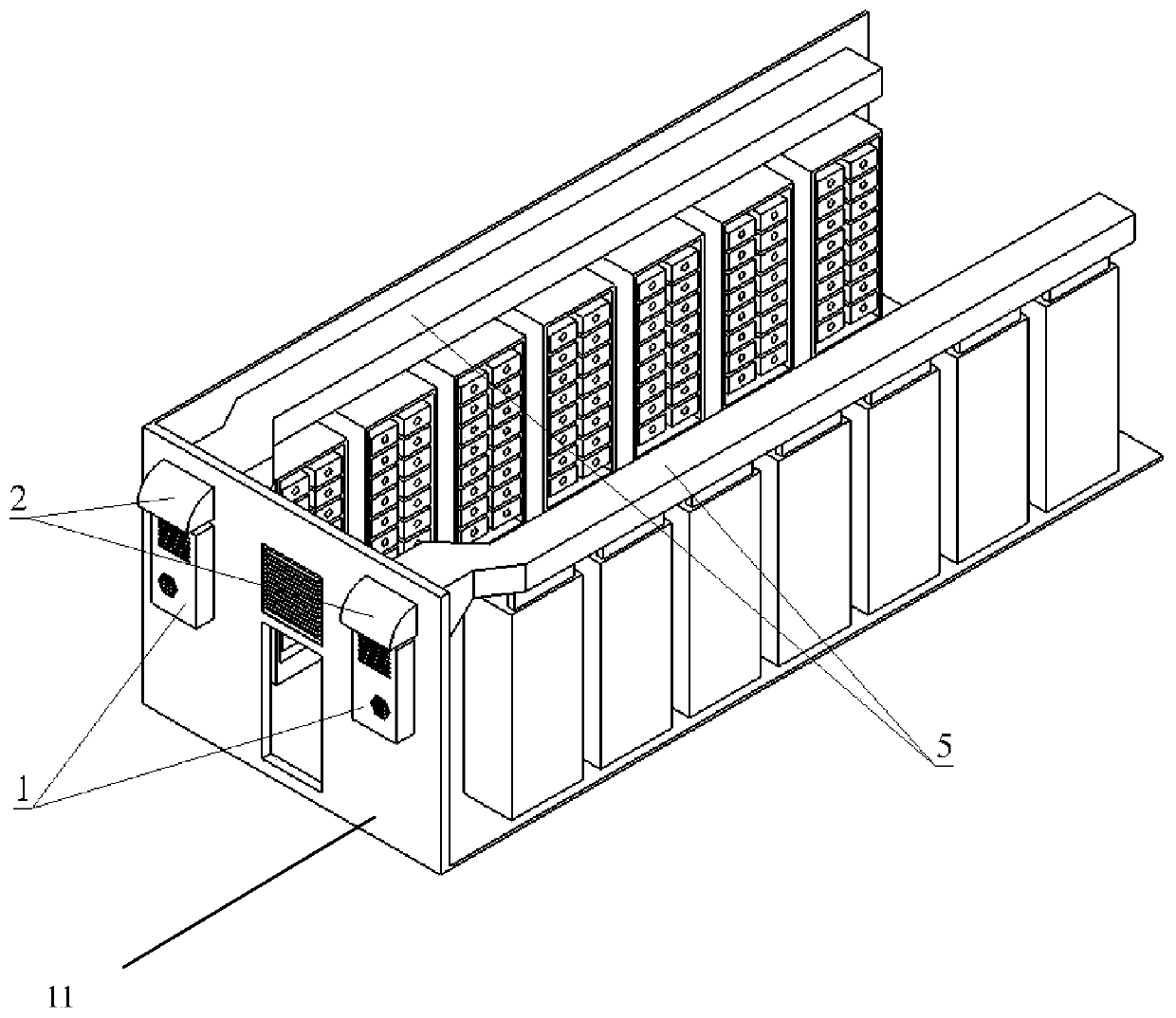
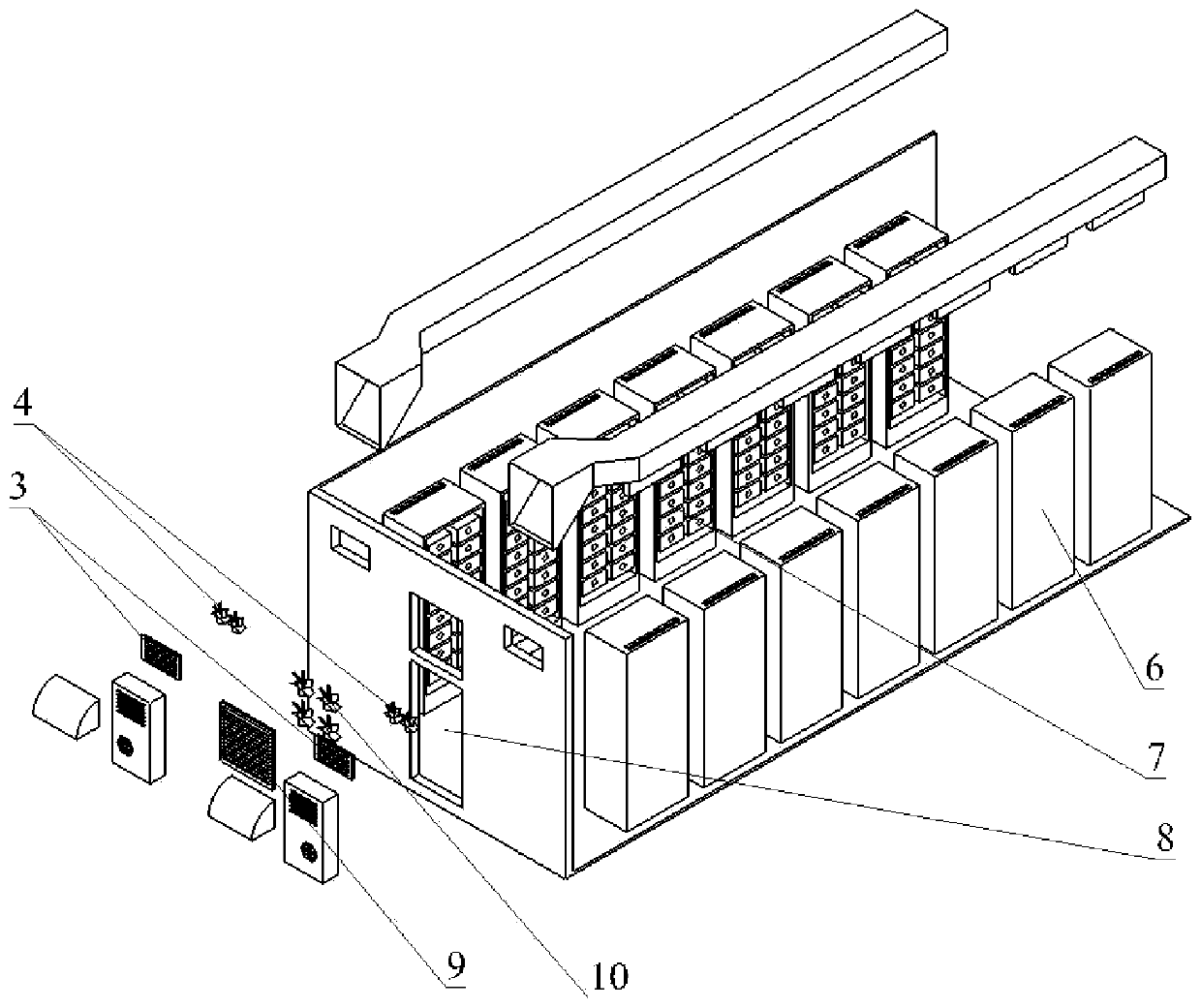
[0032] Such as figure 1 with figure 2 The shown temperature control system for an energy storage container adopts the following technical scheme:

[0033] The temperature control system includes a box body 11 and a control part matched with the box body 11. The inside of the box body 11 is provided with a number of battery cabinets, a number of battery modules, and an air duct part, and the air duct part includes an air inlet channel , heat dissipation air duct and air outlet air duct, several air conditioners 1 are installed on the outer wall of the box body 11 or in the inner space, wherein the air outlet of each air conditioner 1 communicates with the air inlet of the air duct part, and the air inlet of each air conditioner 1 The air outlet communicates with the air outlet of the air duct part, and an external air intake module composed of a first electric louver 3 a...


PUM


Abstract

The invention provides an energy storage container temperature control system and a temperature control method. The temperature control system comprises an air inlet part, an air outlet part, a control part and an air duct part in a box body, and an external air inlet module and an air outlet of an air conditioner are jointly used as an air inlet part. The external air inlet module is composed ofa first electric shutter installed on the air inlet channel and a plurality of air inlet fans. An external air outlet module and an air inlet of each air conditioner jointly serve as an air outlet part, the external air inlet module is composed of a second electric shutter installed on an air outlet channel and a plurality of air outlet fans, an air outlet of each air conditioner is communicated with an air inlet of an air duct part, and an air inlet of each air conditioner is communicated with an air outlet of the air duct part. The system power consumption is greatly reduced while the battery operation storage temperature is ensured, the working efficiency of the energy storage system is effectively improved, and the product income is improved; and meanwhile, the air-conditioner utilization rate is reduced, and the air-conditioner service life is prolonged.

Description

technical field [0001] The invention belongs to the technical field of electric energy storage, and in particular relates to an energy storage container temperature control system and a temperature control method. Background technique [0002] In recent years, with the increasing frequency regulation, demand regulation, peak shaving of power plants, and the demand for wind and new energy, the demand for power storage system products is increasing. Among them, lithium battery energy storage products are characterized by their high performance, long life, clean and non-toxic. Advantages such as pollution become the first choice. [0003] However, after a series of project verifications, although the efficiency of lithium battery energy storage products is higher than that of other energy storage systems, there is still a large energy loss. In addition to inevitable losses such as internal resistance, the power consumption of system thermal management has a particularly obviou...

Claims


Application Information

Patent Timeline
Patent Type & Authority Applications(China)
IPC IPC(8): H01M10/48H01M10/635H01M10/6563H01M10/663H01M10/42
CPCH01M10/425H01M10/486H01M10/635H01M10/6563H01M10/663H01M2010/4271H01M2010/4278Y02E60/10
Inventor 杨永兴张艳
Owner 江苏安靠能源装备有限公司
Why Eureka
Try Eureka