Power supply cabinet capable of automatically lifting

A technology for automatic lifting and power supply cabinets, which is applied in the direction of lifting frames, lifting devices, substation/power distribution device shells, etc., can solve the problems of power supply cabinets without fire-fighting devices, which cannot be solved immediately, and potential safety hazards, so as to ensure safety. The mechanism is simple and the effect of improving the safety factor

Active Publication Date: 2020-04-10
WUYI XIANHE ELECTRONICS CO LTD
5 Cites 0 Cited by

AI-Extracted Technical Summary

Problems solved by technology

However, some existing power supply cabinets require maintenance workers to go up to a high place for maintenance, which poses a great safety hazard. If the power supply is placed on a level g...

Abstract

The invention discloses a power supply cabinet capable of automatically lifting. The cabinet comprises a machine body and a box body arranged above the machine body; a power cavity is formed in the machine body. A power device is arranged in the power cavity. A transmission cavity is formed in the machine body. A transmission device is arranged in the transmission cavity; a connecting rod cavity is formed in the box body. A connecting rod device is arranged in the connecting rod cavity. An operation cavity is formed in the box body. A smoke sensor is arranged in the operation cavity. A controlcavity is formed in the machine body. The power supply cabinet is simple in structure and easy and convenient to use, automatic lifting of the power supply cabinet is achieved through mechanical transmission control, the safety of maintenance workers is guaranteed, meanwhile, based on application of a sensor, the power supply cabinet can solve the problem in the first time when facing a fire, andthe safety coefficient is greatly improved.

Application Domain

Substation/switching arrangement casingsLifting frames

Technology Topic

Safety coefficientPower apparatus +2

Image

  • Power supply cabinet capable of automatically lifting
  • Power supply cabinet capable of automatically lifting
  • Power supply cabinet capable of automatically lifting

Examples

  • Experimental program(1)

Example Embodiment

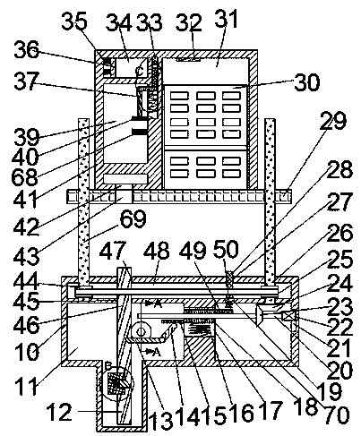
[0014] Combine below Figure 1-4 The present invention will be described in detail. For the convenience of description, the following directions are specified as follows: figure 1 The vertical, horizontal, front, and rear directions of the projection relationship are the same.
[0015] Reference Figure 1-4 According to an embodiment of the present invention, a power supply cabinet that can be automatically raised and lowered includes a body 10 and a box body 41 disposed above the body 10, and a power chamber 70 is provided in the body 10, and the power chamber 70 is A power device is provided. The body 10 is provided with a transmission cavity 48, the transmission cavity 48 is provided with a transmission device, the box body 41 is provided with a connecting rod cavity 39, and the connecting rod cavity 39 is provided with a connecting rod. Rod device, the box body 41 is provided with an operating chamber 31, the operating chamber 31 is provided with a smoke sensor 32, the body 10 is provided with a control chamber 11, and the control chamber 11 is provided with a control device, so The control device includes a first sliding groove 45 arranged on the upper wall of the control cavity 11, a gear plate 46 extending up and down is provided in the first sliding groove 45, and a rectangular block 57 is fixedly connected to the gear plate 46, The rectangular block 57 is provided with a second sliding groove 60, the second sliding groove 60 is provided with a control block 59, the end surface of the control block 59 is provided with an inclined surface, and the control block 59 is connected to the control block 59 through the first spring 58. The inner wall of the second sliding groove 60 is connected, the rear wall of the control chamber 11 is rotated with a spindle 56, the spindle 56 is fixedly provided with a gear 55 meshing with the rack plate 46, and the spindle 56 is fixedly provided with Worm gear 52, the right wall of the control chamber 11 is provided with a third sliding groove 17, the third sliding groove 17 is provided with a control slide 18, and the lower end of the control slide 18 is connected to the third The inner wall of the sliding groove 17 is connected, the control slide 18 is rotated with a worm 20 extending left and right, the left side of the control slide 18 is fixedly connected with a first control block 15, and the front wall of the control cavity 11 is fixed with a support rod 53. The supporting rod 53 is provided with a first rotating rod 13 which is rotatably arranged on the end surface of the first rotating rod 13 with a slope. The right side of the first rotating rod 13 is fixedly connected with a second rotating rod 14, and the box The upper side of the body 41 is provided with a pressure chamber 34, the pressure chamber 34 is filled with carbon dioxide, the right wall of the pressure chamber 34 is provided with a port 66 communicating with the operation chamber 31, and the pressure chamber 34 is provided with a compression plate 36 The compression plate 36 is connected to the left inner wall of the pressure chamber 34 through the third spring 35.
[0016] In addition, in one embodiment, the power device includes a fourth sliding groove 21 provided on the inner wall of the right side of the power chamber 70, and a motor 22 is provided in the fourth sliding groove 21, and the left end of the motor is connected to the The worm 20 is connected with a driving bevel gear 23, the upper wall of the power chamber 70 is provided with a first threaded shaft 26 extending upward, and the lower end of the first threaded shaft 26 is provided with the driving bevel gear 23. The driven bevel gear 24 meshed with the bevel gear 23 is provided with a second control rod 49 in the power chamber 70, and the left end of the second control rod 49 is fixedly connected with the control slider 18.
[0017] In addition, in one embodiment, the transmission device includes a second threaded shaft 69 rotatably arranged on the upper wall of the transmission cavity 48, and a left timing pulley 44 is fixed on the second threaded shaft 69, and the first The threaded shaft 26 is fixedly provided with a right timing pulley 25, the right timing pulley 25 and the left timing pulley 44 are connected by a belt drive, and the upper part of the body 10 is provided with the first threaded shaft 26 and the second The support plate 29 is threadedly connected with the threaded shaft 69, the support plate 29 is fixed with an operation panel 30, the support plate 29 is fixed with a sliding groove 43, and the upper wall of the transmission cavity 48 is provided with a fifth sliding groove 27, The fifth sliding groove 27 is provided with a third control rod 28, the lower wall of the control cavity 48 is provided with a sixth sliding groove 19, the third control rod 28 is located in the sixth sliding groove 19, the first The lower end of the three control rod 28 is connected to the second control rod 49 through a fourth spring 50.
[0018] In addition, in one embodiment, the connecting rod device includes a seventh sliding groove 64 provided on the inner wall of the right side of the connecting rod cavity 39 and an eighth sliding groove 33 provided on the upper wall of the seventh sliding groove 54. The eighth sliding groove 33 is provided with a baffle 65, the baffle 65 is provided with an opening 67, the lower end of the baffle 65 is provided with a first connecting rod 61, and the lower end of the first connecting rod 61 is fixedly connected with The second connecting rod 37 is fixedly connected to the lower end of the second connecting rod 37 with a magnet 40, the lower end of the first connecting rod 61 is provided with a fifth spring 63 connected to the lower wall of the seventh sliding groove 64, the connecting rod An electromagnet 68 is fixed on the inner wall on the right side of the cavity 39, and the smoke sensor 32 controls the operation of the electromagnet 68.
[0019] In the initial state, the first spring 58, the second spring 16, the fourth spring 50, and the fifth spring 63 are all in a normal state, the third spring 35 is in a compressed state, and the active cone The gear 23 meshes with the driven bevel gear 24, and the worm gear 52 does not mesh with the worm 20.
[0020] When the operation panel 30 catches fire: the smoke sensor 32 activates the electromagnet 68, moves the magnet 40, the second link 37, and the first link 61 downward, and the A connecting rod 61 drives the baffle 65 to move downward, so that the opening 67 is the same as the through port 66. At this time, the pressure chamber 34 is released, and the compression plate 36 is under the action of the third spring 35. Move to the right to squeeze the carbon dioxide in the pressure chamber 34 into the operation chamber 31;
[0021] When the power supply cabinet needs to be repaired, start the motor 22, the motor 22 drives the worm 20 to rotate, the worm 20 drives the driving bevel gear 23 to rotate, and the driving bevel gear 23 drives the driven bevel gear 24 rotates, the driven bevel gear 24 drives the first threaded shaft 26 to rotate, the first threaded shaft 26 drives the right timing pulley 25 to rotate, and the right timing pulley 25 drives the left timing pulley 44 to rotate , The left timing pulley 44 drives the second threaded shaft 69 to rotate, so that the support plate 29 moves downward, and then the box body 41 moves downward, when the support plate 29 is lowered to the bottom end , The support plate 29 presses the third control rod 28, the third control rod 28 is pressed down, and the second control rod 49 is moved downward by the fourth spring 50, and the second control The rod 49 drives the control slide 18 and the first control rod 15 to move downwards, and the control slide 18 drives the worm 20, the driving bevel gear 23 and the motor 22 to move downwards, thereby causing the The driving bevel gear 23 is disengaged from the driven bevel gear 24, the worm gear 52 meshes with the worm 20, the worm gear 52 drives the main shaft 56 to rotate, and the main shaft 56 drives the gear 55 to rotate, so that the The rack plate 12 moves upward, and the rack plate 12 drives the box body 41 to move upward, exposing the operating panel 30;
[0022] When reset is needed: the motor 22 reverses, the motor 22 drives the worm 20 to rotate, the worm 20 drives the worm gear 52 to rotate, and the worm gear 52 drives the main shaft 56 and the gear 55 to rotate, Thus, the rack plate 12 is moved downward, thereby resetting the supporting plate 29. When the rack plate 12 is lowered to the lower end, the control block 59 contacts the first rotating rod 13, thereby causing the first The rotating lever 13 and the second rotating lever 14 rotate counterclockwise, the second rotating lever 14 pushes the first control lever 15 upward, and the first control lever 15 drives the control slider 18 to move upward, The control slider 18 drives the worm 20 to move upward, so that the driving bevel gear 23 meshes with the driven bevel gear 24, the worm gear 52 is disengaged from the worm 20, and the driving bevel gear 23 drives The driven bevel gear 24 rotates, the driving bevel gear 23 drives the driven bevel gear 24 to rotate, the driven bevel gear 24 drives the first threaded shaft 26 to rotate, and the first threaded shaft 26 drives The right timing pulley 25 rotates, the right timing pulley 25 drives the left timing pulley 44 to rotate, and the left timing pulley 44 drives the second threaded shaft 69 to rotate, thereby resetting the support plate 29.
[0023] The above are only preferred embodiments of the present invention and are not intended to limit the present invention. Any modification, equivalent replacement, improvement, etc. made within the spirit and principle of the present invention shall be included in the present invention Within the scope of protection.

PUM

no PUM

Description & Claims & Application Information

We can also present the details of the Description, Claims and Application information to help users get a comprehensive understanding of the technical details of the patent, such as background art, summary of invention, brief description of drawings, description of embodiments, and other original content. On the other hand, users can also determine the specific scope of protection of the technology through the list of claims; as well as understand the changes in the life cycle of the technology with the presentation of the patent timeline. Login to view more.

Similar technology patents

Dispensing machine positioning method

InactiveCN107537728Asimple organizationlow cost
Owner:常州萱娜电子科技有限公司

Foxing placing device of ceramic tile packaging equipment

ActiveCN105857740Asimple organizationlow cost
Owner:凯米特新材料科技有限公司

Simple test tube cleaning device

InactiveCN111069211Asimple organizationeasy to use
Owner:温州厦贤科技有限公司

Classification and recommendation of technical efficacy words

  • simple organization
  • easy to use

Laser assisted total joint arthroplasty

InactiveUS20090234360A1easy to use
Owner:ALEXANDER VLADIMIR

Enclosure for a portable hemodialysis system

ActiveUS20090114582A1easy to use
Owner:DEKA PROD LLP
Why Eureka
Try Eureka