Stator structure with self-adaptive magnetic field correction capability
A stator structure, self-adaptive technology, applied in the direction of magnetic circuit shape/style/structure, magnetic circuit, magnetic circuit static components, etc., can solve the problem of inability to automatically correct the fault magnetic field, low winding utilization, and inability to adapt to and other problems, to achieve the effect of automatically correcting the faulty magnetic field and improving the ability of fault-tolerant operation.
- Summary
- Abstract
- Description
- Claims
- Application Information
AI Technical Summary
Problems solved by technology
Method used
Image
Examples
Embodiment 1
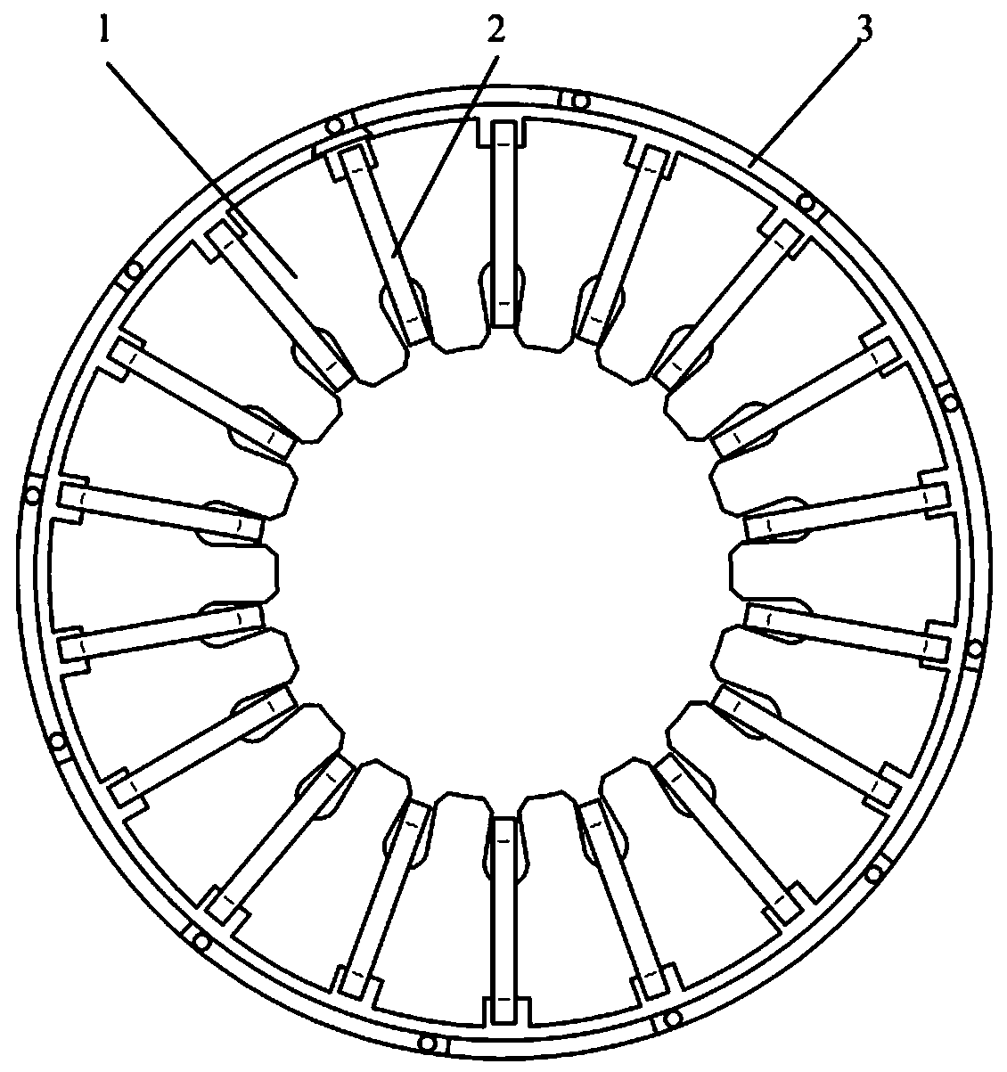
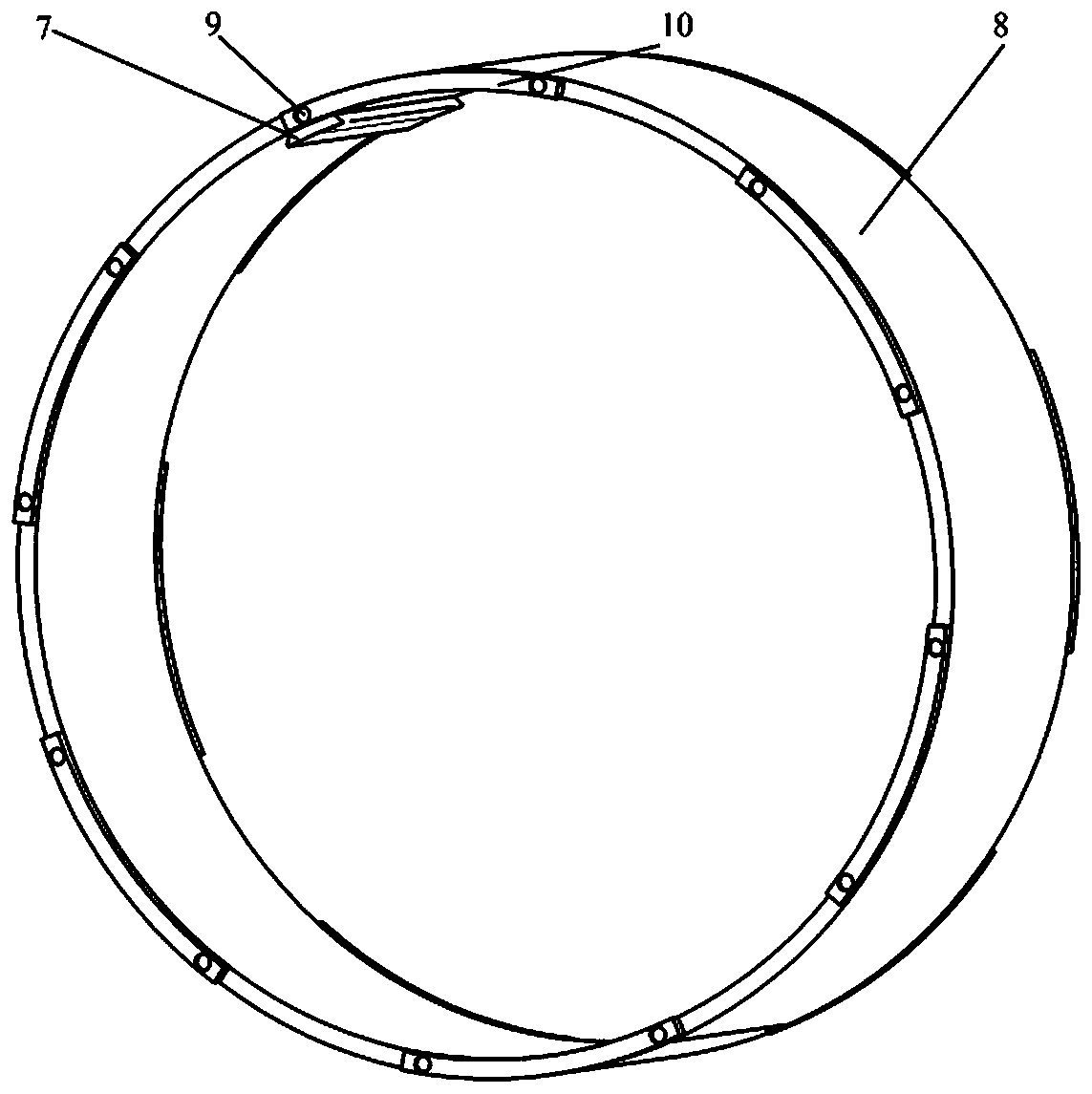
[0037] Such as Figure 1 to Figure 7As shown, this embodiment discloses a stator structure with adaptive magnetic field correction capability, including a bidirectional slotted stator 2, m-symmetrical wraparound windings 1 and an adaptive magnetic field correction ring 3, where m is the phase of the motor number.
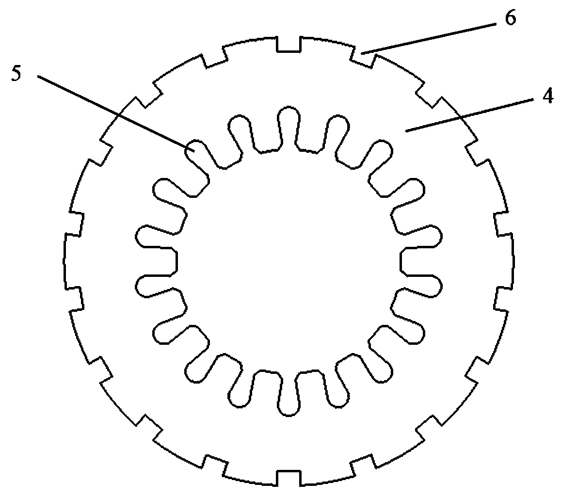
[0038] There are slots on both sides of the two-way slotted stator, including stator yoke 4, stator inner slot 5 and stator outer slot 6. The number of slots in the stator inner slot 5 is 2pmk, and the slots in the stator inner slot 5 are slotted at equal intervals in the circumferential direction. The stator outer slots 6 are slotted on the back of the stator, and the number of the stator outer slots 6 is equal to 2pmk. The stator outer slots 6 are radially outwardly opened, and are also slotted at equal intervals in the circumferential direction. Among them, p is the number of pole pairs of the motor, and k is a positive integer.
[0039] The center line of the...
Embodiment 2
[0054] According to actual needs, slots of different depths can be opened on the back of the stator.
[0055] Such as Figure 8 As shown, the difference between this embodiment and Embodiment 1 is that the slot depth of the stator outer slot 6 is different, and the wrap-around winding 1 is embedded in the slot with different depth of the stator outer slot, which increases the adjustment range of the induced electromotive force, thereby increasing Correction effect.
Embodiment 3
[0057] Such as Figure 9 As shown, the difference between the present embodiment and the first embodiment is that the number of correction teeth is increased by 7, and the adjustment range of the induced electromotive force is increased, thereby increasing the correction effect.
PUM
 Abstract
Description
Claims
Application Information
 - R&D
- Intellectual Property
- Life Sciences
- Materials
- Tech Scout
- Unparalleled Data Quality
- Higher Quality Content
- 60% Fewer Hallucinations
Browse by: Latest US Patents, China's latest patents, Technical Efficacy Thesaurus, Application Domain, Technology Topic, Popular Technical Reports.
© 2025 PatSnap. All rights reserved.Legal|Privacy policy|Modern Slavery Act Transparency Statement|Sitemap|About US| Contact US: help@patsnap.com


