Micro motor protection device

A technology of micro-motors and protection devices, applied in the direction of electromechanical devices, electrical components, electric components, etc., can solve problems such as easy to be knocked, small size, small capacity, damage to motor parts, etc., to achieve sufficient protection, easy and fast installation and disassembly Effect

Inactive Publication Date: 2020-04-10
衡阳市大力成泵业制造有限责任公司
View PDF6 Cites 3 Cited by
  • Summary
  • Abstract
  • Description
  • Claims
  • Application Information

AI Technical Summary

Problems solved by technology

[0002] Micro motor is a type of motor with small volume and capacity, output power generally below several hundred watts, and special requirements for use, performance and environmental conditions. Micro motors are often used in control systems or transmission mechanical loads to realize electromechanical Functions such as signal or energy detection, analytical calculation, amplification, execution or conversion, micro motors need to be widely used in life and production, and need to be carefully stored. Micro motors are precision instruments. Due to their small size, It is easy to carry, so it is very easy to be bumped, which will cause damage to the internal parts of the motor

Method used


Image

  • Micro motor protection device
  • Micro motor protection device
  • Micro motor protection device

Examples


Embodiment 1

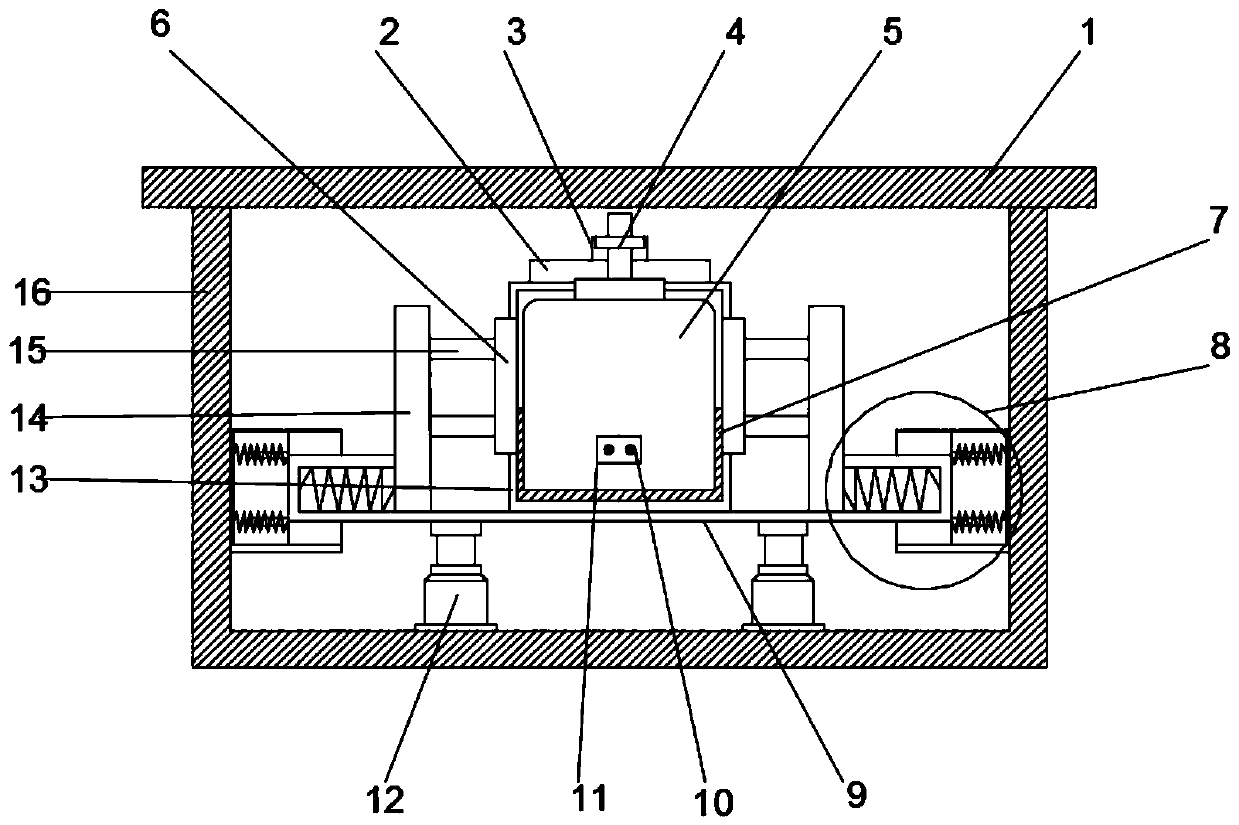
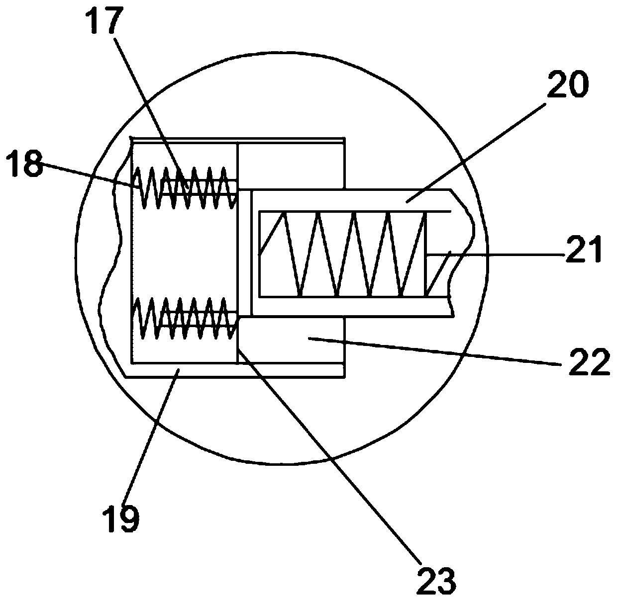
[0020] see Figure 1-3 , a miniature motor protective device, including a protective cover 1 and a protective box 16, the protective cover 1 and the protective box 16 are connected by bolts, the bottom of the protective box 16 is fixedly installed with a buffer hydraulic rod 12, the buffer hydraulic rod 12 is about There is one each, the tops of the two buffer hydraulic rods 12 are connected to the fixed plate 9, the two ends of the fixed plate 9 are respectively provided with a clamping plate 14, and the two ends of the fixed plate 9 and the side wall of the protective box 16 are installed with buffer devices 8. A buffer plate 19 is connected to the bottom of the buffer device 8 and the side wall of the protective box 16. The two buffer plates 19 have buffer grooves 22 on one side close to each other. The buffer groove 22 is slidably connected to the moving plate 23. A plurality of limit blocks 17 are welded to the side of the plate 23 away from the buffer groove 22 . A buffe...

Embodiment 2

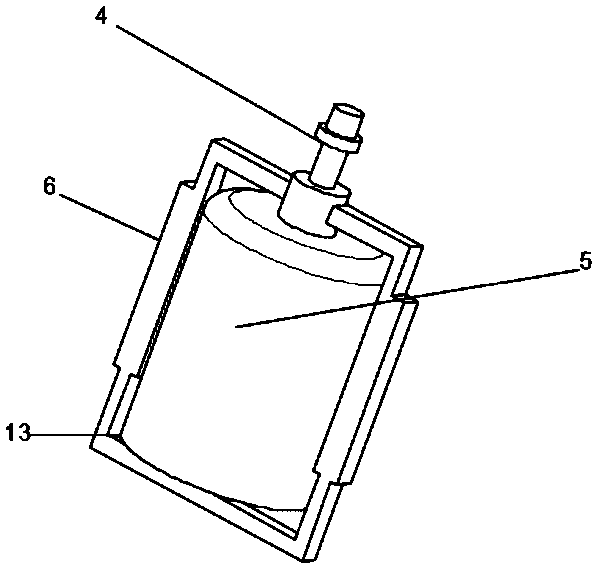
[0025] like figure 1 , figure 2 , in order to better protect the body of the micro motor 5, a protective structure 13 is installed outside the micro motor 5, and two sets of wires extending to the outside of the protective structure 13 are connected to the wire connection cover 11 on the top of the micro motor body 5 10. The wire connection cover 11 is convenient for the power supply connection of the micro motor body 5, the wire 10 is convenient for the connection between the micro motor body 5 and the power supply, and a fixing sleeve 6 is fixedly installed in the middle of the protective structure 13, which can improve the power supply to the micro motor 5. For protection, the fixing sleeve 6 extends upward to connect with the micro motor 5 , and the front cover 2 is installed on the upper part of the micro motor 5 .

[0026] Further, in order to improve the stability of the protection structure 13 for the protection of the micro motor 5 , in this embodiment, a layer of p...


PUM


Abstract

The invention discloses a micro motor protection device. The micro motor protection device comprises a protective cover, the protective cover is connected with a protective box through bolts, and thebuffer hydraulic rods are fixedly mounted at the bottom of the protection box. The top of the buffer hydraulic rod is connected with a fixing plate, clamping plates are arranged at the two ends of thefixing plate, and buffering devices are installed at the two ends of the fixing plate and the side wall of the protection box. Two fixed shafts are fixedly mounted at the sides, close to each other,of the two clamping plates, when a micro motor is installed, a compression spring generates an elastic force to fix the micro motor on the fixing plate through a fixing shaft. The buffering devices are fixedly connected at the two sides of the clamping plates and the inner wall of the protection box, and by utilizing a plurality of buffering springs, the side wall of the micro motor is protected.The two buffer hydraulic rods are installed at the bottom of the fixing plate, so that the bottom of the fixing plate can be buffered when being impacted. According to the technical design, the micromotor is protected more fully and comprehensively, and the installation and detachment are more convenient and faster.

Description

technical field [0001] The invention relates to the technical field of motor protection, in particular to a miniature motor protection device. Background technique [0002] Micro motor is a kind of motor with small volume and small capacity, output power generally below hundreds of watts, and special requirements for use, performance and environmental conditions. Micro motors are often used in control systems or transmission mechanical loads to realize electromechanical Signal or energy detection, analytical operation, amplification, execution or conversion and other functions, micro motors need a wide range of applications in life and production, and need to be stored carefully. Micro motors are precision instruments. Due to their small size, It is easy to carry, so it is very easy to be bumped, resulting in damage to the internal parts of the motor. SUMMARY OF THE INVENTION [0003] The purpose of the present invention is to provide a micro-motor protection device to so...

Claims


Application Information

Patent Timeline
Patent Type & Authority Applications(China)
IPC IPC(8): H02K5/00H02K5/04H02K5/24
CPCH02K5/00H02K5/04H02K5/24
Inventor 阳志华黎瑞胡轩成
Owner 衡阳市大力成泵业制造有限责任公司
Why Eureka
Try Eureka