Valve protective cover convenient to disassemble

A protective cover and valve technology, applied in valve details, valve devices, pipeline protection and other directions, can solve the problems of valves being easily damaged by freezing, high cost, and inconvenient to disassemble, so as to reduce the probability of freezing damage and increase the use of The effect of longevity and easy disassembly

Inactive Publication Date: 2021-02-26
西安沃唯隆控制系统有限公司
View PDF2 Cites 2 Cited by
  • Summary
  • Abstract
  • Description
  • Claims
  • Application Information

AI Technical Summary

Problems solved by technology

[0006] 1. The valve protective cover is troublesome to install, and it is inconvenient to disassemble after covering it, and the replacement cost is high. If it is not replaced in time, the valve still cannot be protected;
[0007] 2. During the use of the valve, the insulation shell is usually required to have a thermal insulation effect on the valve. The thermal insulation effect of this equipment is not obvious. When the valve is in a low temperature working environment, the valve protective cover cannot play a good role in the valve. Protective effect, the valve is easily damaged by freezing

Method used


Image

  • Valve protective cover convenient to disassemble
  • Valve protective cover convenient to disassemble
  • Valve protective cover convenient to disassemble

Examples


Embodiment 1

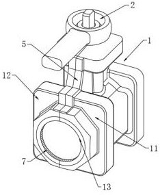
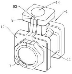
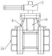
[0035] Example 1 see Figure 1-7 , the present invention provides the following technical solutions: a valve shield that is easy to disassemble, including: the valve body 2, the shell 1 and the clamping mechanism 9 are composed of three parts.

[0036] Wherein the valve body 2 is a metal casting;

[0037] The shell 1 is assembled from detachable parts, including a front cover 11 and a rear cover 12, the front cover 11 is formed on the left side of the valve body 2, the rear cover 12 is formed on the right side of the valve body 2, the front cover The bottom of shell 11 and rear cover 12 is provided with hinge 3, and hinge 3 is respectively fixedly connected between front cover 11 and rear cover 12 by bolt, and the bottom of front cover 11 and rear cover 12 is connected by hinge 3 rotation The front cover 11 and the rear cover 12 are symmetrical stainless steel covers, and the front cover 11 and the rear cover 12 can cover the valve body 2 for protecting the valve body 2 .

...

Embodiment 2

[0041] Embodiment 2 is on the basis of embodiment 1 such as figure 2 As mentioned above, the joint portion of the front cover 11 and the rear cover 12 encloses a horizontal through hole 13 extending in the horizontal direction and a vertical through hole 14 vertically communicating with the horizontal through hole 13 .

[0042] In this embodiment: in order to fit the valve body 2, the horizontal perforation 13 is used to accommodate the valve body, and the vertical perforation 14 is used for the valve stem to pass upwards.

Embodiment 3

[0043] Embodiment 3 is such as on the basis of embodiment 1 figure 2 As mentioned above, the inner wall of the horizontal perforation 13 along the two ends along the length direction and the inner wall of the vertical perforation 14 are provided with rubber rings 7 .

[0044]In this embodiment: in order to ensure the tightness between the valve body 2 and the casing 1, rubber rings 7 are arranged on the inner walls of the openings of the horizontal perforation 13 and the vertical perforation 14, and the rubber rings 7 are provided to seal the valve body 2. The gap between the valve body and the shell 1 prevents the corrosion of the internal valve body 2 due to excessive gap.


PUM


Abstract

The invention provides a valve protective cover convenient to disassemble, and belongs to the technical field of valve protective covers. The valve protective cover convenient to disassemble comprisesa valve body, a shell, a front housing and a rear housing; the shell is formed by assembling detachable parts and comprises a front housing and a rear housing; the front housing is formed at the outer side of the valve body; the rear housing is formed at the inner side of the valve body; hinges are arranged at the bottom of the front housing and the bottom of the rear housing, and the bottom of the front housing is rotatably connected with the bottom of the rear housing through the hinges; the interior of the shell is of a cavity structure, a heat preservation medium is arranged in the cavitystructure, the front housing and the rear housing are hinged to the valve body through hinges, the valve body is located in a horizontal through hole defined by the front housing and the rear housing, and a valve rod upwards penetrates through a vertical through hole defined by the front housing and the rear housing, and the front housing and the rear housing are fixed through bolts, so that thedisassembly is convenient, and a valve is comprehensively protected.

Description

technical field [0001] The technical field of the valve protection cover of the present invention, in particular relates to a valve protection cover which is easy to disassemble. Background technique [0002] The valve is a control component in the fluid delivery system. It has the functions of cut-off, reverse flow, reverse flow prevention, pressure stabilization, diversion or overflow pressure relief, etc. It is used for the valve of the fluid control system. From the simplest cut-off valve to various valves used in extremely complex automatic control systems, there are quite a variety of varieties and specifications. Valves can be used to control the flow of various types of fluids such as air, water, steam, various corrosive media, mud, oil, liquid metal and radioactive media. [0003] The invention with the existing application number CN201711256975.0 discloses a valve protective cover, which includes an outer cover and a cover plate. Side plates are connected to the l...

Claims


Application Information

Patent Timeline
Patent Type & Authority Applications(China)
IPC IPC(8): F16K27/12F16L59/16
CPCF16K27/12F16L59/161
Inventor 张辞源
Owner 西安沃唯隆控制系统有限公司
Why Eureka
Try Eureka