
Power module for a converter and multilevel converter

A multi-level converter and power module technology, which is applied in the direction of converting AC power input to DC power output, output power conversion devices, electrical components, etc., and can solve problems such as faults

Active Publication Date: 2020-04-10
SIEMENS ENERGY GLOBAL GMBH CO & KG
View PDF9 Cites 0 Cited by
  • Summary
  • Abstract
  • Description
  • Claims
  • Application Information

AI Technical Summary

Problems solved by technology

In addition, faults can occur, for example due to a short circuit, which affect the entire converter and thus all power modules

Method used


Image

  • Power module for a converter and multilevel converter
  • Power module for a converter and multilevel converter
  • Power module for a converter and multilevel converter

Examples


Embodiment Construction

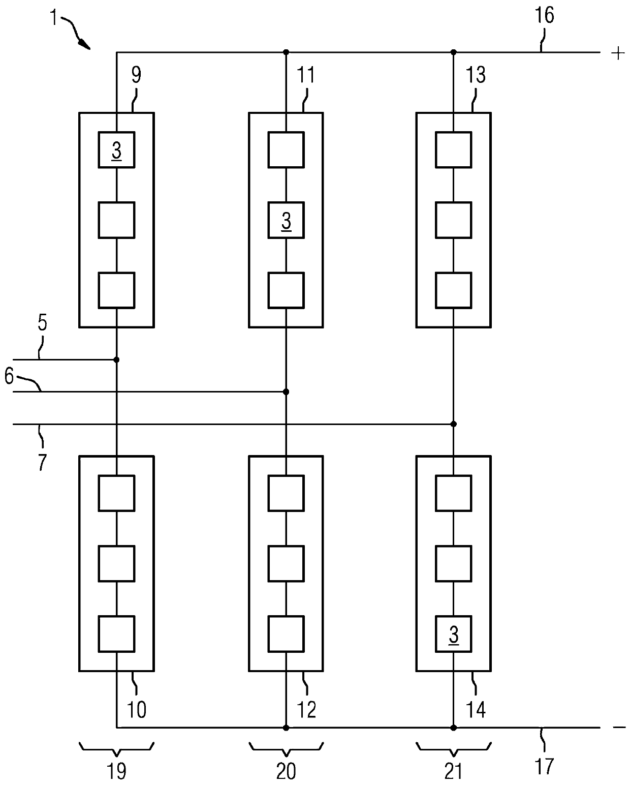
[0019] figure 1 A circuit diagram of an embodiment of the converter 1 is shown. The converter 1 is designed as a three-phase modular multilevel converter with a plurality of power modules 3 . The converter 1 has a first AC voltage connection 5 , a second AC voltage connection 6 and a third AC voltage connection 7 .

[0020] The first AC voltage connection 5 is electrically connected to the first phase module branch 9 and the second phase module branch 10 . The first phase module branch 9 and the second phase module branch 10 form a first phase module 19 of the converter 1 . The end of the first phase module branch 9 facing away from the first AC voltage connection 5 is electrically connected to a first DC voltage connection 16 . The end of the second phase module branch 10 facing away from the first AC voltage connection 5 is electrically connected to a second DC voltage connection 17 . The first DC voltage connection 16 is a positive DC voltage connection. The second DC ...


PUM


Abstract

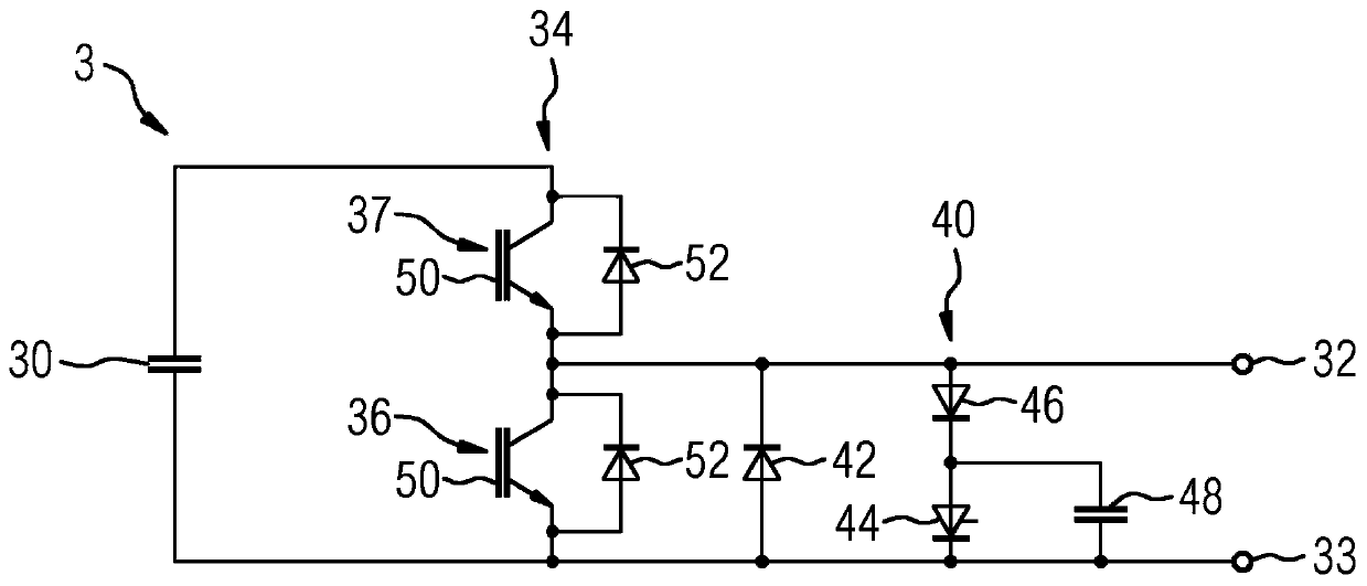
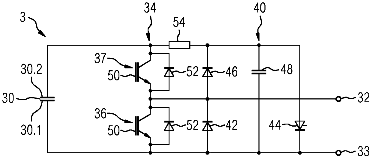
The invention relates to a power module (3) for a converter (1), in particular for a multilevel converter. The power module (3) comprises a link circuit capacitor (30), two connection terminals (32, 33), at least one half-bridge (34) connected in parallel with the link circuit capacitor (30) and having two semiconductor switches (36, 37), and, for each half-bridge (34), a bypass diode (42) connected in parallel with a first semiconductor switch (36) of the half-bridge (34) and a load-relief circuit group (40) connected in parallel with the first semiconductor switch (36), which load-relief circuit group comprises a load-relief thyristor (44) and a load-relief diode (46) connected in series with the load-relief thyristor (44).

Description

technical field [0001] The invention relates to a power module for a converter and a multilevel converter. Background technique [0002] A multilevel converter is understood to be a converter which generates an output voltage which (for each phase of the converter) can each assume at least three voltage values. Compared with conventional two-level converters, multilevel converters have the advantage, for example, that an output voltage with low harmonics is generated. Modular multilevel converters have a number of power modules connected in series, which are also referred to as submodules. The power modules of modular multilevel converters have to be designed for different fault situations. If, for example, a fault situation occurs at the power module level, due to which the power module is no longer operable, it must be possible to remove the power module from the series circuit. In addition, faults can occur, for example due to a short circuit, which affect the entire c...

Claims


Application Information

Patent Timeline
Patent Type & Authority Applications(China)
IPC IPC(8): H02M1/32
CPCH02M1/32H02M7/483
Inventor H-G.埃克尔D.施密特F.施雷默M.瓦尔
Owner SIEMENS ENERGY GLOBAL GMBH CO & KG
Learn More