Supercharge Your Innovation With Domain-Expert AI Agents!

Filtering treatment system for printing and dyeing sludge and operation method thereof

A technology for printing and dyeing sludge and treatment system, which is applied in the field of flue gas purification and can solve problems such as affecting the effect of flue gas purification.

Active Publication Date: 2020-04-14
杭州萧越染织有限公司
View PDF7 Cites 0 Cited by
  • Summary
  • Abstract
  • Description
  • Claims
  • Application Information

AI Technical Summary

Problems solved by technology

[0004] The present invention aims to solve the problem that the flue gas purification device of the existing boiler purifies the flue gas, because the flue gas contains a large number of particles, and the large amount of particles in the flue gas affects the flue gas purification effect. Finally, the flue gas is separated from the solid smoke first, and then the flue gas that has been separated from the solid smoke is sent to the flue gas purification device for flue gas purification, and the degree of solid smoke separation can be freely controlled for printing and dyeing Sludge filtration treatment system and its operation method

Method used


Image

  • Filtering treatment system for printing and dyeing sludge and operation method thereof
  • Filtering treatment system for printing and dyeing sludge and operation method thereof
  • Filtering treatment system for printing and dyeing sludge and operation method thereof

Examples


Embodiment 1

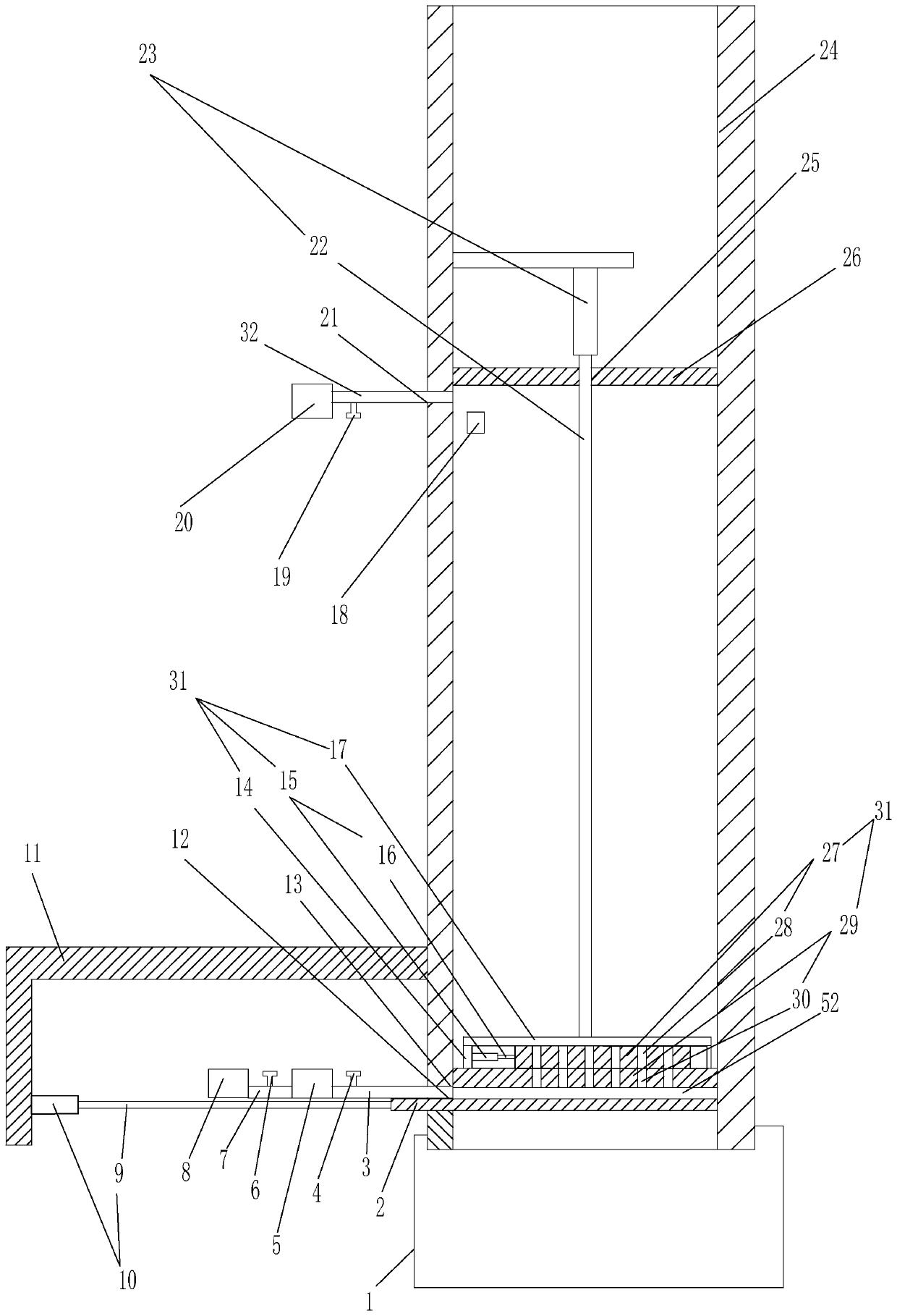
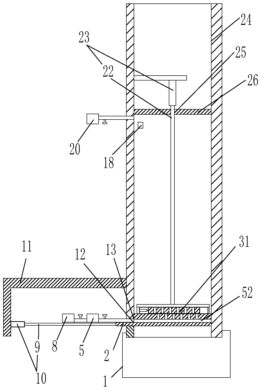
[0091] Embodiment 1, is used for the filter treatment system of printing and dyeing sludge, see figure 1 , Figure 23 shown. Comprising a boiler 8 capable of burning printing and dyeing sludge and a flue gas purification device 20, and also including a No. 1 vertical pipe 24 with a rectangular cross-section of the inner lumen, a smoke extractor 5, a storage device 33 and a controller 34; A left bracket 11 is provided on the left side outer tube wall of the tube, and a No. 1 cylinder 10 with a telescopic rod arranged to the right is arranged on the left bracket;

[0092] The lower end of the left pipe wall of the No. 1 vertical pipe is provided with a No. 1 flue gas inlet 13 communicating with the lumen of the No. 1 vertical pipe; The two ends are butt-connected to the flue gas inlet of the hood and the flue gas outlet of the boiler respectively, and the two ends of a No. 2 flue gas communication pipe 3 with No. 2 valve 4 are butt-connected to the flue gas outlet of the hood ...

Embodiment 2

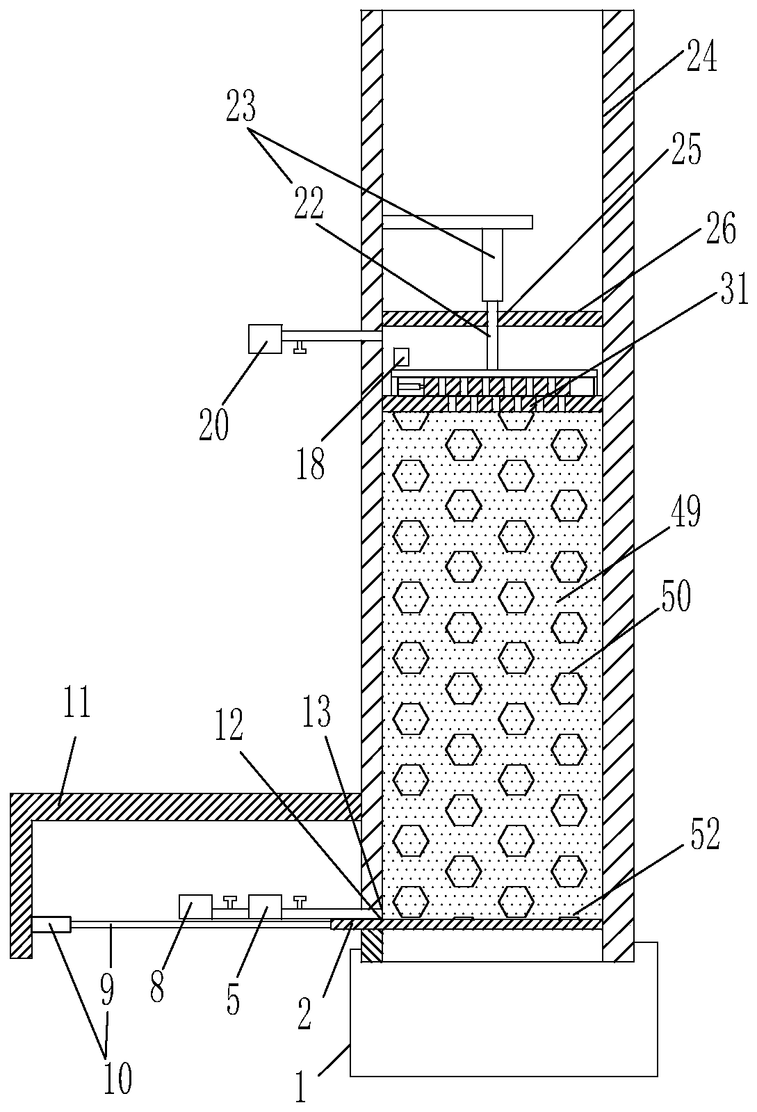
[0139] Embodiment 2, the difference between embodiment 2 and embodiment 1 are as follows:

[0140] A No. 1 groove 36 is provided on the left inner wall of the No. 1 vertical pipe located below the limit block and above the No. 1 flue gas inlet hole, and a No. 1 lamp 37 is arranged in the No. 1 groove. In the notch of the No. 1 groove on the outside side, the No. 1 light-transmitting glass sheet 38 whose outer surface and the left inner wall surface of the No. 1 vertical tube are in the same vertical plane is sealed; The wall is provided with a No. 2 groove 41, and the No. 1 groove and the No. 2 groove are horizontally opposite to each other; the No. 1 photoelectric sensor 42 is arranged in the No. 2 groove, and the No. The notch of the groove is airtightly provided with the No. 2 light-transmitting glass sheet 43 whose outer surface is in the same vertical plane as the left inner wall surface of the No. 1 vertical pipe; Both the groove and the No. 2 groove are located below t...


PUM


Abstract

The invention discloses a filtering treatment system for printing and dyeing sludge and an operation method of the filtering treatment system, belongs to the technical field of flue gas purification,and aims to realize solid-flue gas separation of flue gas after the flue gas comes out of a boiler, sending of the flue gas subjected to solid-flue gas separation into a flue gas purification device for flue gas purification, and free control of the solid-flue gas separation degree. The system comprises the boiler and the flue gas purification device, and further comprises a first vertical pipe with an inner pipe cavity with a rectangular cross section, a smoke sucker, a storage device and a controller; a left support is arranged on the outer pipe wall of the left side of the first vertical pipe, and a first air cylinder with a rightward telescopic rod is arranged on the left support.

Description

technical field [0001] The invention relates to the technical field of flue gas purification, in particular to a filtration treatment system for printing and dyeing sludge and an operation method thereof. Background technique [0002] At present, in the treatment of boiler flue gas, the flue gas from the boiler is generally directly introduced into the flue gas purification device for flue gas purification, but each time the flue gas sent to the flue gas purification device contains a large amount of Particles, and the amount of particles contained in the flue gas entering the flue gas purification device at different time periods is different, but the flue gas purification device adds purifying agents to purify the flue gas according to the same purification treatment requirements at every moment Yes, and the amount of particles in the flue gas and the size of the particles have a greater impact on the purification effect of the flue gas purification. [0003] Larger parti...

Claims


Application Information

Patent Timeline
IPC IPC(8): B01D46/10B01D46/44B01D46/00B01D46/48F23G7/00
CPCB01D46/0054B01D46/10B01D46/442B01D46/48F23G7/001F23G2209/12
Inventor 汪国锋
Owner 杭州萧越染织有限公司
Features
  • R&D
  • Intellectual Property
  • Life Sciences
  • Materials
  • Tech Scout
  • Unparalleled Data Quality
  • Higher Quality Content
  • 60% Fewer Hallucinations
Learn More