Modular test box for experiment sample of space material

A modular and test box technology, applied in the field of aerospace material exposure experiments, can solve problems affecting the smooth progress of other material exposure experiments, and achieve the effects of facilitating installation and water removal, small size, and low weight

Active Publication Date: 2020-04-14
TECH & ENG CENT FOR SPACE UTILIZATION CHINESE ACAD OF SCI
View PDF4 Cites 2 Cited by
  • Summary
  • Abstract
  • Description
  • Claims
  • Application Information

AI Technical Summary

Problems solved by technology

[0024] The technical problem to be solved by the present invention is that the existing devices used for space material exposure experiments outside the cabi...

Method used


Image

  • Modular test box for experiment sample of space material
  • Modular test box for experiment sample of space material
  • Modular test box for experiment sample of space material

Examples


Embodiment 1

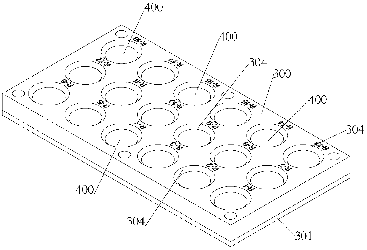
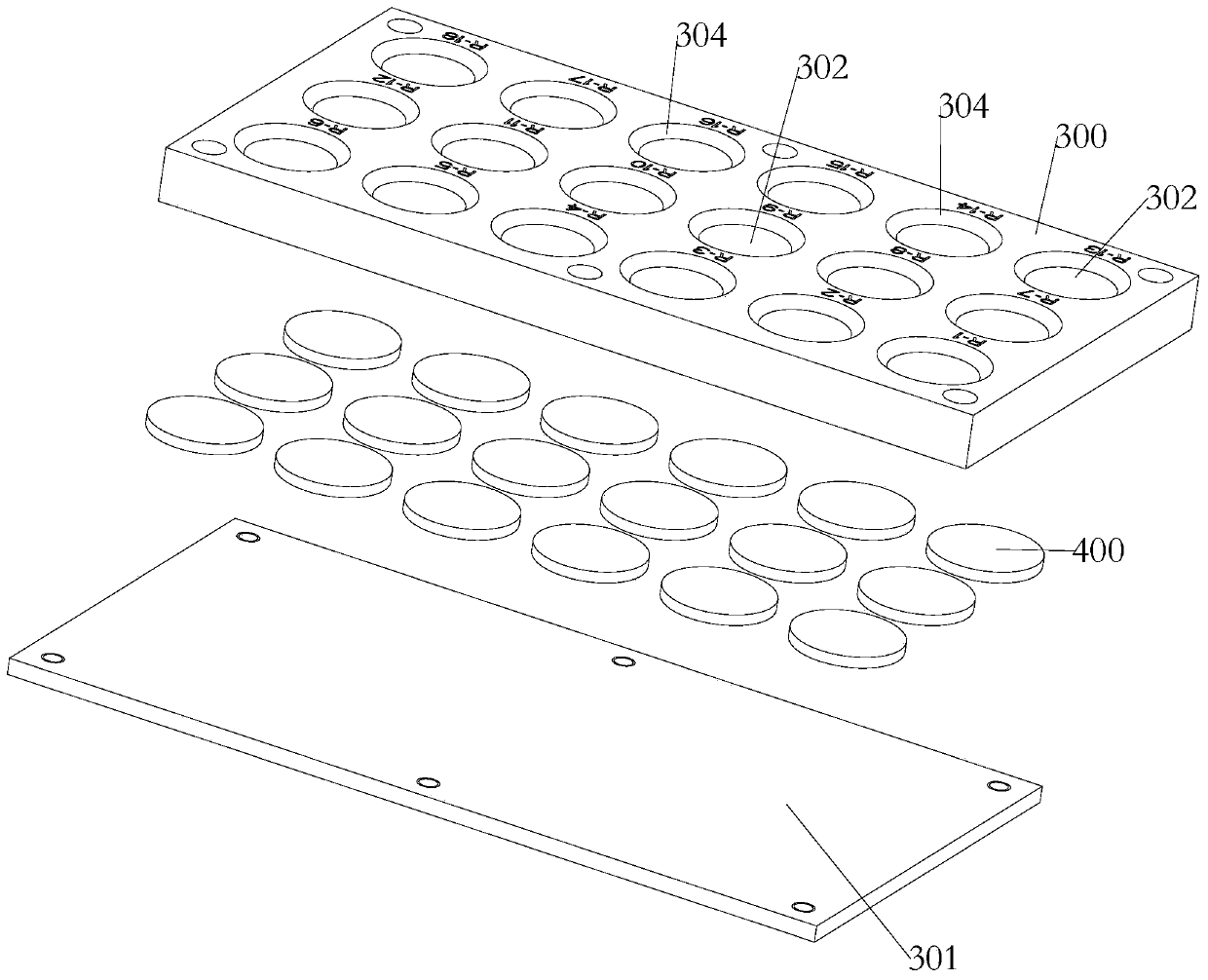
[0156] Such as Figure 2-Figure 4 As shown, this embodiment mainly relates to a general material module, the sample material is a general material, the installation support structure includes an upper cover 300 and a lower cover 301, and the upper cover 300 is provided with a number of exposure holes 302, the On the inner ring side of the upper end of the exposure hole 302, there is a circle of crimping edge 303, and the upper end of the crimping edge 303 is provided with a circle of chamfering 304 near the position of the exposing hole 302, and the specific chamfering angle is 45°; the lower cover plate 301 is detachable Installed on the lower end of the upper cover 300 , an installation space for installing materials is formed between the lower cover 301 and the pressing edge 303 .

[0157] Such as Figure 2-Figure 4 As shown, the general material of this embodiment is adapted to be installed in the installation space. The sample module of this embodiment can be used for e...

Embodiment 2

[0159] Such as Figure 5-Figure 8 As shown, the present embodiment mainly involves the functional material module, the sample material is a functional material, the installation support structure includes an upper cover 300 and a lower cover 301, and the upper cover 300 is provided with a number of exposure holes 302, so The upper end of the exposed hole 302 is provided with a circle of bevels 303 on the inner ring side, and the upper end of the bezels 303 is provided with a circle of chamfers 304 near the position of the exposed holes 302, and the specific design of the chamfers is 45°; the lower cover plate 301 can be It is disassembled and installed at the lower end of the upper cover plate 300 , and an installation space for installing materials is formed between the lower cover plate 301 and the pressing edge 303 .

[0160] Such as Figure 5-Figure 8As shown, the installation support structure of this embodiment also includes an O-ring 305, an isolation ring 306 and a su...

Embodiment 3

[0165] Such as Figure 9-Figure 11 As shown, the present embodiment mainly involves polymer material modules, and the installation support structure includes an upper cover plate 300 and a lower cover plate 301, and several exposure holes 302 are opened on the upper cover plate 300, and the upper ends of the exposure holes 302 are A circle of bevel 303 is provided on the inner ring side, and a circle of chamfer 304 is provided at the upper end of the bezel 303 close to the exposure hole 302, and the chamfer is specifically designed to be 45°; the lower cover 301 is detachably mounted on the At the lower end of the upper cover plate 300 , an installation space for installing materials is formed between the lower cover plate 301 and the pressing edge 303 .

[0166] Such as Figure 9-Figure 11 As shown, the installation support structure of this embodiment also includes a spacer plate 308 and an elastic support plate 309, the elastic support plate 309 is located above the lower ...


PUM


Abstract

The invention relates to a modular test box for an experiment sample of a space material. The modular test box comprises a box body, a box cover, a mounting tray and a plurality of sample modules, thebox cover is hinged to the box body, sample trays are mounted on the inner sides of the box body and the box cover respectively; each sample module comprises a mounting supporting structure and a sample material, the mounting supporting structure is detachably connected to the mounting tray, the sample material is limited and supported on the mounting supporting structure, and the exposed surfaceof the sample material is arranged towards the side deviating from the mounting tray. The test box can realize in-orbit tests of a material in extremely harsh environments such as space atomic oxygendenudation, space high and low temperature alternation, space high-energy particle radiation, microgravity, ultrahigh vacuum, space debris/micro-meteor body impact, and the like. Meanwhile, ground laboratory installation, water removal, gas removal, dust removal treatment, on-orbit disassembly and replacement and disassembly operation after returning to the ground are facilitated; and the aerospace characteristic requirements of compact structure, small size, light weight and reliable mechanical property in the rocket launching ascending stage are met.

Description

technical field [0001] The present invention relates to the technical field related to aerospace material exposure experiments, specifically to the interdisciplinary research fields of space material science and space physics science, and specifically to a modular test box for space material experiment samples. Background technique [0002] After investigation, it was found that famous foreign aerospace agencies such as NASA, Russian Aerospace Agency (RSA), European Space Agency (ESA), Japan Aeronautics and Space Agency (JAXA), etc., conduct material exposure tests based on the International Space Station (ISS). As well as the development of the sample experiment module, according to different test purposes and requirements, a variety of material on-orbit test devices are designed for material systems such as metallic materials, inorganic non-metallic materials, polymer materials, and composite materials. In China, no relevant work has been retrieved on the development of sp...

Claims


Application Information

Patent Timeline
IPC IPC(8): B01L1/00
CPCB01L1/00
Inventor 张伟贵张聚乐王乐天王珂乔志宏杨鹏邓明哲
Owner TECH & ENG CENT FOR SPACE UTILIZATION CHINESE ACAD OF SCI
Why Eureka
Try Eureka