
Motor shaft manufacturing process

A manufacturing process and motor shaft technology, applied in the field of metal processing, can solve the problems of the central hole of the motor shaft not being located in the central position, high production cost, no pre-positioning of the motor shaft, etc., to achieve the effect of ensuring accuracy and improving machining accuracy

Active Publication Date: 2021-01-08
重庆登阳机电有限公司
View PDF11 Cites 0 Cited by
  • Summary
  • Abstract
  • Description
  • Claims
  • Application Information

AI Technical Summary

Problems solved by technology

[0004] The present invention intends to provide a motor shaft manufacturing process to solve the problem that the center position of the motor shaft is not pre-positioned before the center hole of the motor shaft is processed, so that the machined center hole of the motor shaft is not located at the center position, resulting in scrapped products , the problem of high production cost

Method used

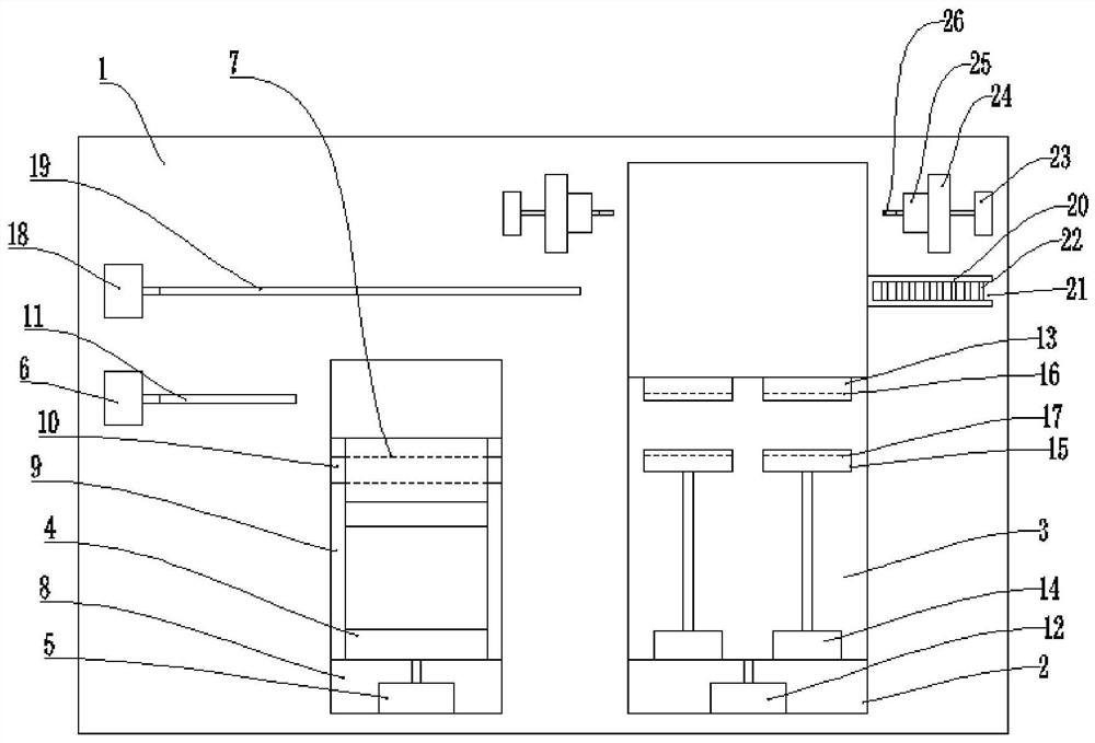

Image

  • Motor shaft manufacturing process
  • Motor shaft manufacturing process
  • Motor shaft manufacturing process

Examples


Embodiment 1

[0036] The manufacturing process of the motor shaft includes the following steps:

[0037] Step 1: Preparation; select a cylindrical iron column with a complete appearance;

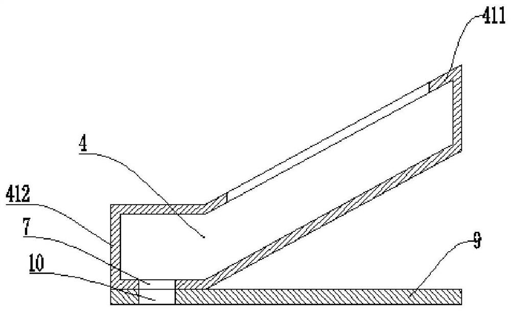
[0038] Step 2: Center hole positioning; center hole positioning device is required, including clamping mechanism and pre-drilling mechanism; the iron column in step 1 is clamped by the clamping mechanism, and the axial direction of the iron column is adjusted by the pre-drilling mechanism. The center position is pre-drilled, so that the axial center position of the iron column has a center slot;

[0039] Step 3: Drilling for the first time; Position the iron column in Step 2, and perform the first drilling process along the path of the central groove;

[0040] Step 4: drilling for the second time; positioning the iron column in step 3, drilling for the second time along the path of the central groove, making the center hole of the iron column, and the center hole runs through the iron column;

[0041] S...

Embodiment 2

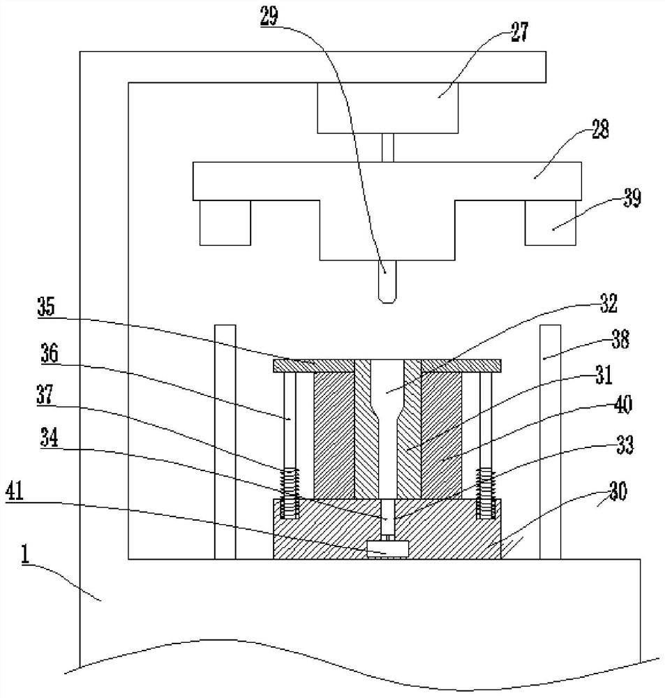
[0064] Basic as attached Figure 4 As shown: the structure and implementation of Embodiment 2 are basically the same as Embodiment 1, the difference is that the diameter reducing device also includes a guide mechanism, and the guide mechanism includes a guide post 42 fixed on the bottom of the stop table 39 and a The guide slot 43 on the top of the positioning post 38 is located on the movement track of the guide post 42 , and the guide post 42 can slide in the guide slot 43 .

[0065] The diameter reducing device also includes a damping mechanism, which includes a damping plate 44 and a spring 45, the damping plate 44 is slidably connected in the guide, and the two ends of the spring 45 are fixedly connected with the damping plate 44 and the guide groove 43 respectively.

[0066] The support column 40 is provided with six vertical grooves 46 in the circumferential direction, and the vertical grooves 46 are arc-shaped;

[0067] The specific implementation process is as follow...


PUM


Abstract

The invention relates to the technical field of metal processing and discloses a motor shaft manufacturing process. The process comprises steps of step 1, preparing, and selecting an iron column; 2, positioning a central hole, specifically a center hole positioning device needs to be used and comprises a clamping mechanism and a pre-drilling mechanism, an iron column is clamped firstly and then pre-drilled, and a center groove is formed in the axial center position of the iron column; 3, drilling for the first time; 4, drilling for the second time; 5, reducing the diameter, a hole shrinkage device needs to be used and comprises an extrusion mechanism and a center column, and a diameter shrinkage hole is formed in the center column; the diameter of the iron column is reduced to obtain a motor shaft. The process is advantaged in that problems that the central position of the motor shaft is not pre-positioned before the central hole of the motor shaft is machined at present, so the machined central hole of the motor shaft is not positioned at the central position, a product is scrapped, and production cost is high are mainly solved.

Description

technical field [0001] The invention relates to the technical field of metal processing. Background technique [0002] The shaft is an important part of the motor. It serves as the link of electromechanical energy conversion between the motor and the equipment, supports the rotating parts, transmits the torque and determines the relative position of the rotating parts to the stator. Therefore, the motor shaft must have reliable strength and rigidity to ensure the realization of preset design functions. [0003] In modern processing technology, all the finishing of the motor shaft is based on the center hole, so the machining accuracy of the center hole will directly affect the machining accuracy of the motor shaft. With the continuous development of motor application technology, the accuracy requirements for the motor shaft Gradually improve. At present, the center position of the motor shaft is not pre-positioned before machining the center hole of the motor shaft, so tha...

Claims


Application Information

Patent Timeline
Patent Type & Authority Patents(China)
IPC IPC(8): B23P15/00H02K15/14
CPCB23P15/00H02K15/14
Inventor 杨刚
Owner 重庆登阳机电有限公司
Learn More