
A shock-absorbing house foundation pouring structure and pouring method thereof

A foundation and house technology, applied in the direction of basic structure engineering, construction, etc., can solve the problems of not having a splicing and fixing structure, not having an extended auxiliary structure, and reducing the overall quality of the house foundation, so as to reduce the impact force, reduce the difficulty of installation, and fix The effect of convenient operation

Active Publication Date: 2020-12-29
CHINA CONSTR 4TH ENG BUREAU 6TH
View PDF1 Cites 0 Cited by
  • Summary
  • Abstract
  • Description
  • Claims
  • Application Information

AI Technical Summary

Problems solved by technology

[0005] In order to overcome the fact that the traditional shock-absorbing house foundation pouring structure does not have an auxiliary buffer structure, when the house foundation is subjected to external impact during the pouring process, the house foundation is prone to deformation and reduces the overall quality of the house foundation; at the same time, the traditional shock-absorbing house foundation The pouring structure adopts an integrated fixed structure design, so that the traditional shock-absorbing house foundation pouring structure does not have a splicing fixed structure, which increases the difficulty of installation of the traditional shock-absorbing house foundation pouring structure; at the same time, the traditional shock-absorbing house foundation pouring structure does not have extension The auxiliary structure reduces the flexibility of the traditional shock-absorbing house foundation pouring structure, and cannot adjust the size of the foundation arbitrarily according to the needs of use, and provides a shock-absorbing house foundation pouring structure

Method used


Image

  • A shock-absorbing house foundation pouring structure and pouring method thereof
  • A shock-absorbing house foundation pouring structure and pouring method thereof
  • A shock-absorbing house foundation pouring structure and pouring method thereof

Examples


Embodiment Construction

[0027] The technical solutions in the embodiments of the present invention will be clearly and completely described below in conjunction with the embodiments of the present invention. Apparently, the described embodiments are only some of the embodiments of the present invention, not all of them. Based on the embodiments of the present invention, all other embodiments obtained by persons of ordinary skill in the art without creative efforts fall within the protection scope of the present invention.

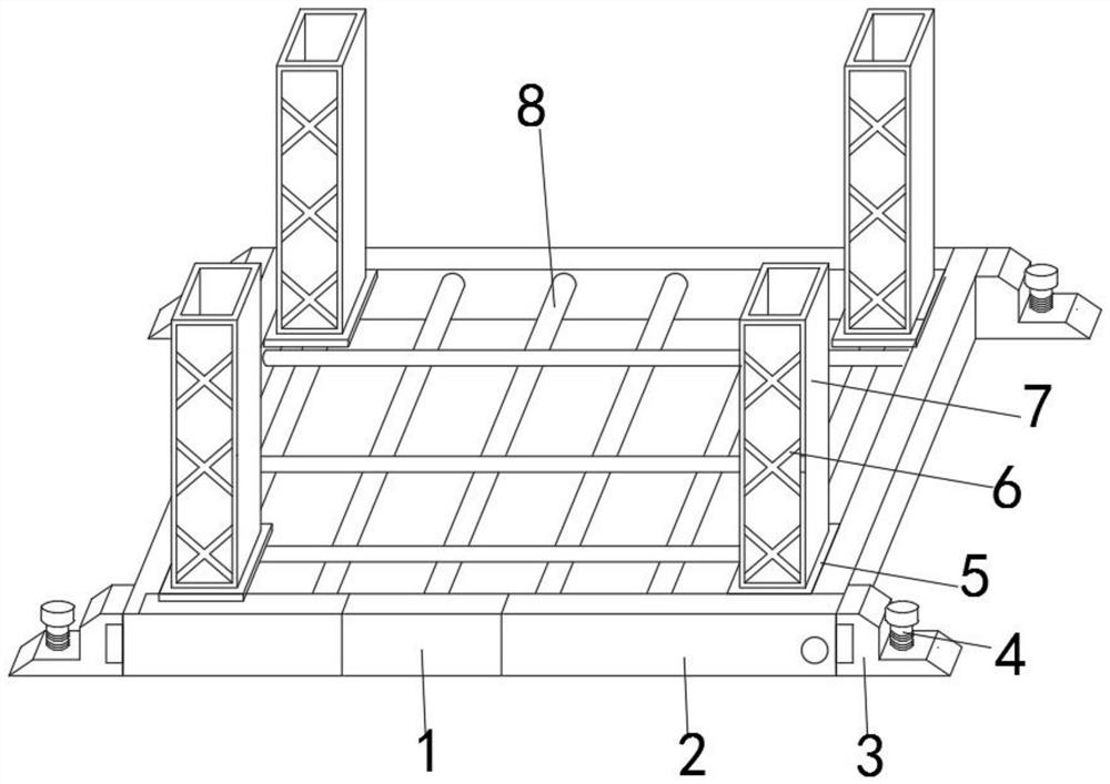
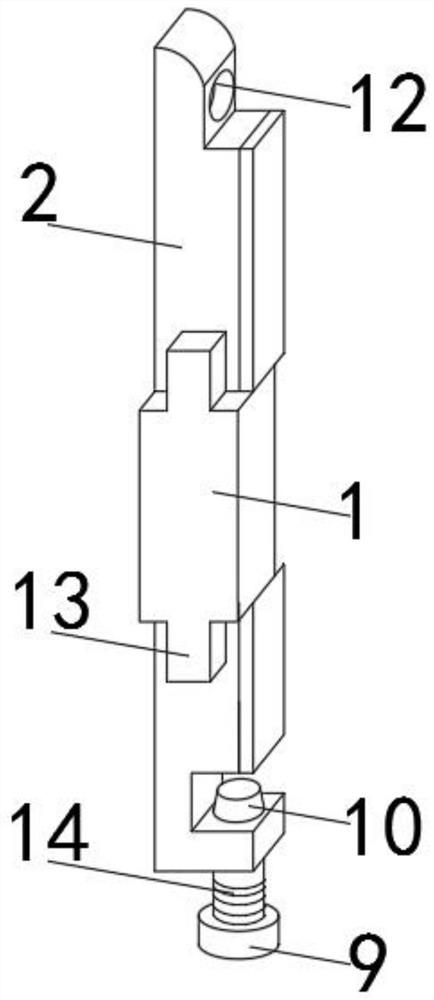
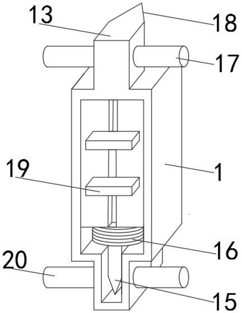
[0028] Such as Figure 1-4As shown, a shock-absorbing house foundation pouring structure includes a fixed side plate 2, a buffer top block 3 and a fixed bottom plate 5, and the buffer top block 3 is movably installed on the outer surfaces of both sides of the fixed side plate 2, and the fixed side plate 2 The splicing clamp 1 is fixedly installed in the middle position of the inner side, and the outer surfaces of both ends of the splicing clamp 1 are fixedly installed with docking...


PUM


Abstract

The invention discloses a shock absorption type house foundation pouring structure. The shock absorption type house foundation pouring structure comprises fixed side plates, buffering top blocks and fixed bottom plates, wherein the buffering top blocks are movably arranged on the outer surfaces of the two sides of the fixed side plates, splicing clamping plates are fixedly arranged in the middlesof the inner sides of the fixed side plates, butt joint clamping heads are fixedly arranged on the outer surfaces of the two ends of the splicing clamping plates, and the fixed side plates and the splicing clamping plates are fixed in a butt joint mode through the butt joint clamping heads, a butt joint circular groove is formed in the inner side of one end of each fixed side plate in a penetrating mode, a fixed ejector pin is movably installed on the inner surface of the lower end of each fixed side plate, the outer surface of each fixed ejector pin is provided with a threaded groove, and thefixed side plates and the fixed ejector pins are movably connected through the threaded grooves. According to the shock absorption type house foundation pouring structure, by means of a shock absorption auxiliary structure, the safety of the shock absorption type house foundation pouring structure is improved; and meanwhile, by means of a splicing fixing structure, the mounting difficulty of theshock absorption type house foundation pouring structure is reduced, and the flexibility of the shock absorption type house foundation pouring structure in use is improved.

Description

technical field [0001] The invention belongs to the technical field of foundation pouring, in particular to a shock-absorbing house foundation pouring structure, more specifically to a shock-absorbing house foundation pouring structure and a pouring method thereof. Background technique [0002] The foundation refers to the soil or rock mass that supports the foundation under the building. The soil layer used as the foundation of the building is divided into rock, gravel soil, sand, silt, clay and artificial filling. The foundation includes natural foundation and artificial foundation Two types, natural foundation is a natural soil layer that does not need to be reinforced by people, and artificial foundation needs to be reinforced by people, such as stone chips cushion, sand cushion, mixed lime soil backfill and then compacted. [0003] The comparative document CN207553130U discloses a molding structure of a secondary pouring foundation, including a concrete foundation, a po...

Claims


Application Information

Patent Timeline
Patent Type & Authority Patents(China)
IPC IPC(8): E02D15/02E02D27/34
CPCE02D15/02E02D27/34
Inventor 翟光耀杨海波向俊志刘芳玲胡晓梅
Owner CHINA CONSTR 4TH ENG BUREAU 6TH
Learn More