
An Optical Measurement System Based on Distributed Optical Fiber Annular Liquid Film Thickness

A distributed optical fiber and liquid film thickness technology, applied in fluorescence/phosphorescence, material analysis through optical means, and measurement devices, can solve the problems of data measurement accuracy, poor real-time measurement, and small propagation speed, etc., to achieve Improve the spatial resolution, the measurement results are true and reliable, and reduce the difficulty

Active Publication Date: 2021-11-30
INST OF MECHANICS - CHINESE ACAD OF SCI
View PDF6 Cites 0 Cited by
  • Summary
  • Abstract
  • Description
  • Claims
  • Application Information

AI Technical Summary

Problems solved by technology

Among them, the first two are contact measurements, which are affected by the surface tension of the liquid film and the interference to the flow. The measurement accuracy is easily affected by the surface liquid film coverage and the structural parameters of the probe, and has interference on the flow field, which is limited. Larger, so although the conductivity method is one of the most commonly used annular flow test methods at present, its intrusive measurement method will inevitably affect the liquid film flow, and has an averaging effect in the measurement area
The ultrasonic method is a non-contact interference-free measurement method. Its measurement principle is that ultrasonic waves have different propagation characteristics and attenuation characteristics in different media, but as a non-electromagnetic wave, ultrasonic waves have relatively small propagation speeds and complex configurations. It will cause multiple reflections in the test piece, which will affect the accuracy of data measurement
And in actual use, the measurement frequency is limited by the ultrasonic attenuation cycle, and the real-time performance of the measurement is not strong

Method used


Image

  • An Optical Measurement System Based on Distributed Optical Fiber Annular Liquid Film Thickness
  • An Optical Measurement System Based on Distributed Optical Fiber Annular Liquid Film Thickness
  • An Optical Measurement System Based on Distributed Optical Fiber Annular Liquid Film Thickness

Examples


Embodiment Construction

[0030] In order to make the purposes, technical solutions and advantages of the embodiments of the present invention clearer, the technical methods in the embodiments of the present invention will be clearly and completely described below with reference to the accompanying drawings in the embodiments of the present invention. Obviously, the described embodiments It is only a part of the embodiments of the present invention, but not all of the embodiments. Based on the embodiments of the present invention, all other embodiments obtained by those of ordinary skill in the art without making creative work results fall within the protection scope of the present invention.

[0031] It should be noted that if there are directional indications (such as up, down, left, right, front, back, etc.) involved in the embodiments of the present invention, the directional indications are only used to explain the relationship between the various components under a certain posture. The relative p...


PUM

PropertyMeasurementUnit
lengthaaaaaaaaaa
lengthaaaaaaaaaa

Abstract

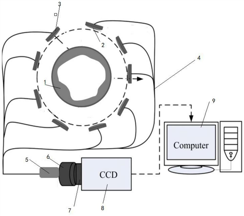
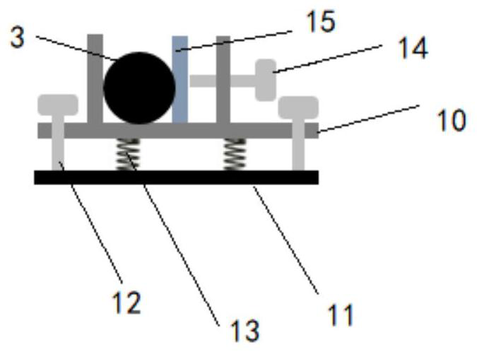
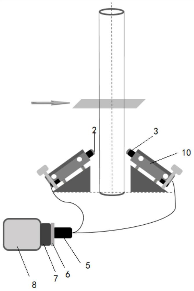
The embodiment of the present invention relates to an optical testing system based on distributed optical fiber annular liquid film thickness, comprising: a liquid film generation module, an acquisition module and an imaging module; the acquisition module is arranged circumferentially outside the liquid film generation module, To collect the fluorescence signal of the liquid film in the liquid film generation module, the output end of the collection module is connected to the imaging module for outputting the fluorescence signal to the imaging module, and the imaging module according to the Fluorescent signals are imaged. Thus, the imaging of the axial thickness and the circumferential thickness can be realized, and the complicated timing synchronization system is omitted, and only the output signal of the laser needs to be used to trigger the enhanced charge coupler to collect. The structure is simple and easy to operate.

Description

technical field [0001] Embodiments of the present invention relate to the field of liquid mode measurement, and in particular, to an optical testing system based on distributed optical fiber annular liquid film thickness. Background technique [0002] The formation and evaporation of liquid films is widespread in various industrial applications, such as oil films on piston heads in engines, oil films on the inner wall of the inlet in gasoline engines, water films in fire-extinguishing applications, and falling film cooling. Because the liquid film flow has the unique advantages of small flow rate, small temperature difference, high heat and mass transfer coefficient, high heat flux density, simple structure and low power consumption, its heat transfer intensity and mass transfer intensity are several times that of laminar flow under the same flow conditions. , has become a very active research field in the international heat and mass transfer science and engineering communit...

Claims


Application Information

Patent Timeline
Patent Type & Authority Patents(China)
IPC IPC(8): G01N21/64
CPCG01N21/6456G01N2021/6463G01N2021/6478
Inventor 王方仪张少华余西龙
Owner INST OF MECHANICS - CHINESE ACAD OF SCI
Learn More