Supercharge Your Innovation With Domain-Expert AI Agents!

Display module

A technology of display modules and light-emitting units, applied in static indicators, instruments, identification devices, etc., can solve problems such as jagged images, and achieve the effect of improving user experience

Inactive Publication Date: 2020-04-14
WUHAN CHINA STAR OPTOELECTRONICS SEMICON DISPLAY TECH CO LTD
View PDF9 Cites 13 Cited by
  • Summary
  • Abstract
  • Description
  • Claims
  • Application Information

AI Technical Summary

Problems solved by technology

[0005] This application provides a display panel and a display module to solve the technical problem of jagged images in the arc area of ​​the existing display panel

Method used


Image

  • Display module
  • Display module
  • Display module

Examples


Embodiment 1

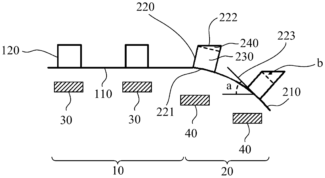
[0051] see figure 2 , the planar region 10 is provided with a plurality of first light-emitting units 120 arranged at intervals on the planar substrate 110, the upper surface and the lower surface of the first light-emitting unit 120 and the planar substrate 110 parallel.

[0052] A plurality of the second light emitting units 220 located on the arc substrate 210 are arranged in the bend, and the second light emitting units 220 are arranged at intervals along the arc substrate 210 .

[0053] In this embodiment, the second light emitting unit 220 includes a first surface 221 in contact with the arc-shaped substrate 210 and a second surface 222 located on the first surface 221 and away from the first surface 221 .

[0054] In this embodiment, the second surface 222 is parallel to the planar substrate 110 .

[0055] In this embodiment, the area of ​​the second surface 222 is equal to the area of ​​the orthographic projection of the first light emitting unit 120 on the planar ...

Embodiment 2

[0064] This embodiment is the same or similar to Embodiment 1, except that:

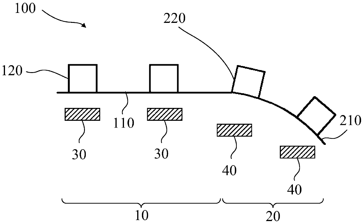
[0065] see image 3 , the shape and size of the first light emitting unit 120 and the second light emitting unit 220 are the same.

[0066] In this embodiment, the first driving device 30 outputs a first voltage to make the first light emitting unit 120 emit light, and the second driving device 40 outputs a second voltage and a compensation voltage to make the second light emitting unit 220 emit light .

[0067] The above-mentioned increase of the compensation voltage increases the luminance of the second light emitting unit 220 , so that the light component of the second light emitting unit 220 in the direction from the planar substrate 110 to the first light emitting unit 120 is different from the light component of the second light emitting unit 220 . The brightness of the first light emitting units 120 in the planar area 10 is consistent.

[0068] In this embodiment, the magnitude of the compe...

Embodiment 3

[0071] This embodiment is the same or similar to Embodiment 1 and Embodiment 2, except that:

[0072] see Figure 4~5 , the display module 100 may further include a compensation layer 50 located on the second light emitting unit 220 . The compensation layer 50 is used to increase the luminance of the second light emitting unit 220 in the direction from the planar substrate 110 to the first light emitting unit 120 .

[0073] see Figure 4 , the compensation layer 50 includes a lens 510 disposed parallel to the curved substrate 210 . The lens 510 is used to refract the light emitted by the second light emitting unit 220 to a direction from the planar substrate 110 to the first light emitting unit 120 .

[0074] In this implementation, an arc-shaped substrate 210 parallel to the arc-shaped substrate 210 can be added to the second light-emitting unit 220 without changing the shape of the second light-emitting unit 220 and the corresponding driving device. , so that the oblique...


PUM


Abstract

The invention provides a display module. The display module comprises a plane area and bending areas located on the two sides of the plane area. A plane substrate and at least one first light-emittingunit located on the plane substrate are arranged in the plane area, and an arc-shaped substrate and at least one second light-emitting unit located on the arc-shaped substrate are arranged in the bending area; and in the direction from the plane substrate to the first light-emitting unit, the light-emitting brightness of the first light-emitting unit is the same as that of the second light-emitting unit. According to the invention, the shape of the second light-emitting unit in the bending area is changed, or / and the driving voltage of the second light-emitting unit is driven, or / and a compensation layer is formed on the bending area. Therefore, the light-emitting brightness of the light-emitting unit in the plane area and the bent area in a display screen is the same, the technical problem of brightness difference or color cast between the bent area and the plane area in an existing curved screen is avoided, and the user experience is improved.

Description

technical field [0001] The present application relates to the display field, in particular to a display module. Background technique [0002] OLED (Organic Light-Emitting Diode, Organic Light-Emitting Diode) displays have advantages that are clearly different from liquid crystal displays, especially their impact on flexible screens. With the development of science and technology, the appearance of mobile electronic devices has undergone tremendous changes. Among them, flexible screens have attracted much attention due to their unique characteristics and huge potential. [0003] The two sides of the existing curved screen and the middle plane are arranged in a certain arc, and due to the light-emitting characteristics of OLED, when viewing the OLED display from different angles of view, there will be a sudden drop in brightness, color shift, etc., resulting in the flat area of ​​the existing curved screen And there is a certain brightness difference in the bending area, whic...

Claims


Application Information

Patent Timeline
IPC IPC(8): G09F9/30G09G3/3208
CPCG09F9/301G09G3/3208
Inventor 颜伟男
Owner WUHAN CHINA STAR OPTOELECTRONICS SEMICON DISPLAY TECH CO LTD
Features
  • R&D
  • Intellectual Property
  • Life Sciences
  • Materials
  • Tech Scout
  • Unparalleled Data Quality
  • Higher Quality Content
  • 60% Fewer Hallucinations
Learn More