
Current-limiting power supply control circuit

A technology of power supply control circuit and delay circuit, applied in the field of electronics

Pending Publication Date: 2020-04-14
常州中海电力科技有限公司
View PDF1 Cites 0 Cited by
  • Summary
  • Abstract
  • Description
  • Claims
  • Application Information

AI Technical Summary

Problems solved by technology

Fuses are generally used to prevent short circuits and not to prevent overloads. Although sampling resistors are a very feasible and effective method, in some circuits with low power consumption and power consumption requirements, the power consumption consumed by sampling resistors cannot be ignored.

Method used


Image

  • Current-limiting power supply control circuit

Examples


Embodiment Construction

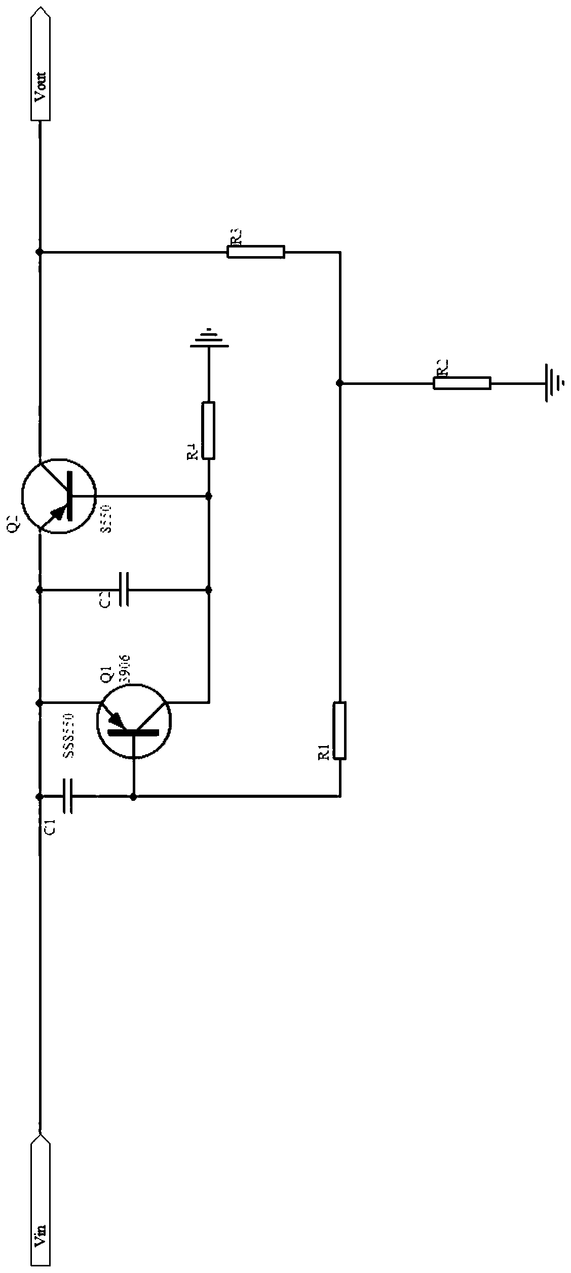
[0013] Such as figure 1 As shown, a current-limiting power supply control circuit of the present invention includes an input terminal and an output terminal, and also includes a PNP transistor Q2, the emitter of the PNP transistor Q2 is connected to the input terminal, and the collector of the PNP transistor Q2 is connected to the input terminal. The output terminal is connected; it also includes a PNP transistor Q1 controlling the base current of the PNP transistor Q2, the emitter of the PNP transistor Q1 is connected to the input terminal, and the collector of the PNP transistor Q1 is connected to the base of the PNP transistor Q2 ; A delay circuit is connected between the input end and the ground to prevent the PNP transistor Q1 and the PNP transistor Q2 from being powered on and self-locking.

[0014] The delay circuit includes a first delay circuit controlling the delay of the PNP transistor Q1 and a second delay circuit controlling the delay of the PNP transistor Q2, and...


PUM


Abstract

The invention relates to the technical field of electronics, and especially relates to a current-limiting power supply control circuit. The circuit comprises an input end, an output end, a PNP triodeQ2 and a PNP triode Q1. An emitter of the PNP triode Q2 is connected with the input end, and a collector of the PNP triode Q2 is connected with the output end; the PNP triode Q1 is used for controlling a current of a base electrode of the PNP triode Q2, the emitter of the PNP triode Q1 is connected with the input end, and the collector of the PNP triode Q1 is connected with the base electrode of the PNP triode Q2; and a time delay circuit for preventing the PNP triode Q1 and the PNP triode Q2 from being electrified and self-locked is connected between the input end and the ground. After the structure is adopted, an amplification effect of the triode is utilized to control a size of a resistor R4 so as to control the base current of the PNP triode Q2 and control the current of the output end; after the PNP triode Q1 is turned on, the output end can normally output only when the input end is powered on again; and the circuit is simple, low in cost and low in power consumption.

Description

technical field [0001] The invention relates to the field of electronic technology, in particular to a current-limited power supply control circuit. Background technique [0002] In many applications, in order to prevent overload, short circuit and other reasons, it is necessary to limit the current and voltage of the output circuit. A common method is to use a fuse or a sampling resistor ADC to read the current limit and prevent short circuits. Fuses are generally used to prevent short circuits and not to prevent overloads. Although sampling resistors are a very feasible and effective method, in some circuits with low power consumption and power consumption requirements, the power consumption of sampling resistors cannot be ignored. [0003] Chinese utility model patent CN 207603267 U discloses a current-limiting control circuit, which includes a voltage reference source U1, a diode D1, a resistor R1, a transistor Q1, and a resistor R2 connected in sequence to form a close...

Claims


Application Information

Patent Timeline
Patent Type & Authority Applications(China)
IPC IPC(8): H02H3/08
CPCH02H3/08
Inventor 王训金季春波纪小刚
Owner 常州中海电力科技有限公司
Learn More