
Power mechanism and hand-held tool using power mechanism

A technology for power mechanisms and tools, applied in manufacturing tools, electromechanical devices, structural connections, etc., can solve problems such as low torque, poor power conversion efficiency, and unstable hand-held tool speed control, reducing risks and achieving stable power conversion efficiency. , Improve the effect of torque

Inactive Publication Date: 2020-04-14
FAIRWAY ELECTRONICS
View PDF5 Cites 0 Cited by
  • Summary
  • Abstract
  • Description
  • Claims
  • Application Information

AI Technical Summary

Problems solved by technology

[0002] Generally speaking, most of the handheld tools currently on the market are directly driven by brushed motors to drive shafts and tool parts (such as grinding discs, drill bits, etc.). However, such a configuration is very poor in terms of power conversion efficiency. For example, The power conversion efficiency of direct drive with brushed motor is only about 40%
In addition, the hand tools in the prior art are not stable in speed control, and the torque they can provide is also very low

Method used


Image

  • Power mechanism and hand-held tool using power mechanism
  • Power mechanism and hand-held tool using power mechanism
  • Power mechanism and hand-held tool using power mechanism

Examples


Embodiment Construction

[0042] The implementation of the present invention is described below with specific examples, and those skilled in the art can easily understand other advantages and effects of the present invention from the content disclosed in this specification. The present invention can also be implemented or applied through other different specific embodiments.

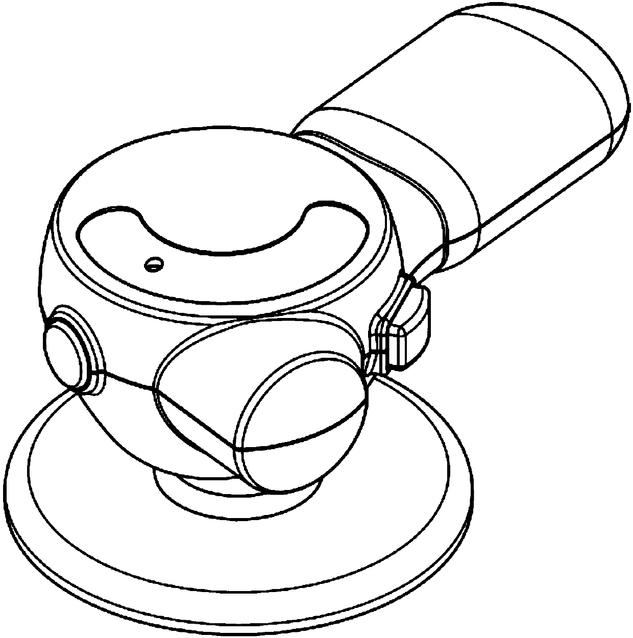
[0043] see figure 1 , figure 1 It is a schematic diagram of the appearance of the hand tool according to the first embodiment of the present invention. The power mechanism of the present invention is applied in such as figure 1 Among the hand tools shown, more specifically, the motor is used as the main power source and the hand tools are convenient to be used by hand.

[0044] Generally speaking, hand-held tools are often used for cleaning, grinding, waxing, etc. Taking cleaning as an example, the tool parts (such as brushes) of the hand-held tool will contact objects and cause friction, so the power mechanism of the hand-hel...


PUM


Abstract

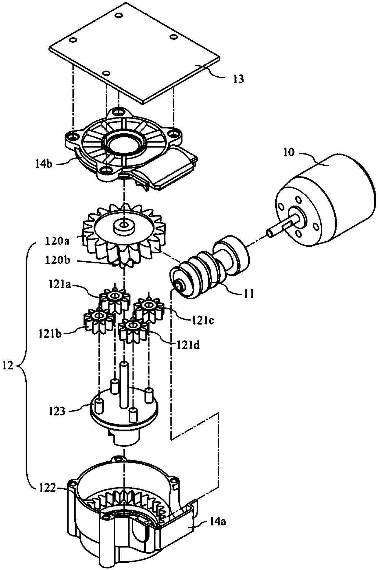
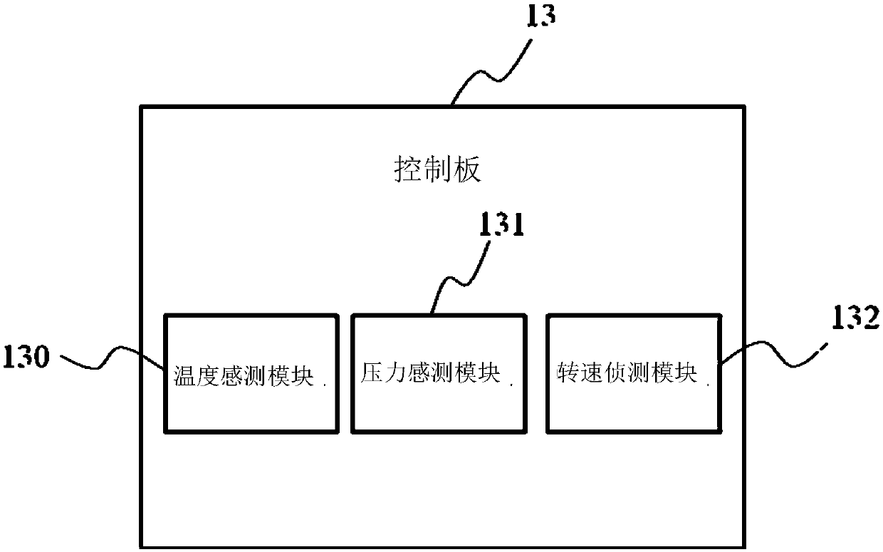
The invention relates to a power mechanism and a hand-held tool using the power mechanism, and the power mechanism comprises a motor, a worm, a planetary gear set and a control panel. The worm is driven by the motor to rotate, the planetary gear set is meshed with the worm, and the control panel is used for controlling the on-off or operation state of the motor.

Description

technical field [0001] The invention relates to a power mechanism and a hand-held tool using the power mechanism, in particular to a power mechanism with a motor as the main power source and a hand-held tool using the power mechanism. Background technique [0002] Generally speaking, most of the handheld tools currently on the market are directly driven by brushed motors to drive shafts and tool parts (such as grinding discs, drill bits, etc.). However, such a configuration is very poor in terms of power conversion efficiency. For example, The power conversion efficiency of a direct drive using a brushed motor is only about 40%. In addition, the hand tools in the prior art are not stable in rotational speed control, and the torque they can provide is also very low. [0003] Therefore, how to provide a power mechanism with high power conversion efficiency, stable rotation speed and high torque, and a hand-held tool using the power mechanism has become an urgent problem in th...

Claims


Application Information

Patent Timeline
Patent Type & Authority Applications(China)
IPC IPC(8): H02K7/116H02K11/20H02K11/21H02K11/25H02K11/33H02K11/38B25F5/00
CPCB25F5/00H02K7/1166H02K11/20H02K11/21H02K11/25H02K11/33H02K11/38
Inventor 阎宁汉谢建雄方郁人
Owner FAIRWAY ELECTRONICS
Learn More