An aeration tank foam treatment device

A technology of treatment device and aeration tank, which is applied in the directions of grease/oily substance/float removal device, liquid degassing, degassing by filtering liquid, etc., which can solve the problem of artificial irregularity and hinder the staff from observing the water level value of sewage treatment status. Measurement accuracy, etc.

Active Publication Date: 2021-12-24
浙江润城环保集团股份有限公司
View PDF7 Cites 0 Cited by
  • Summary
  • Abstract
  • Description
  • Claims
  • Application Information

AI Technical Summary

Problems solved by technology

[0003] During the operation of the aeration tank, when the gas forces the sewage to roll and react, foam will be generated on the surface of the sewage, and the foam will also be mixed with sludge, which will cause accumulation on the surface of the sewage during the aeration process. More foam, the existence of foam will hinder the staff from observing the sewage treatment status and the accuracy of water level measurement, so that the foam generated during the aeration process needs to be manually processed from time to time to keep the water surface clean

Method used


Image

  • An aeration tank foam treatment device
  • An aeration tank foam treatment device

Examples


Embodiment Construction

[0016] Next, the technical solutions in the embodiments of the present invention will be described in connection with the drawings of the embodiments of the present invention, and it is understood that the described embodiments are merely the embodiments of the present invention, not all of the embodiments.

[0017] In the description of the present invention, it is to be understood that the terms "upper", "lower", "front", "post", "left", "right", "top", "bottom", "inside", " The orientation or position of the instructions such as "is based on the orientation or positional relationship shown in the drawings, which is merely intended to describe the present invention and simplified description, rather than indicating or implying that the device or component must have a specific orientation. Specific orientation configurations and operations are not to be understood as limiting the invention.

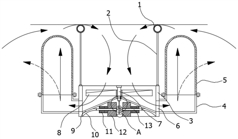
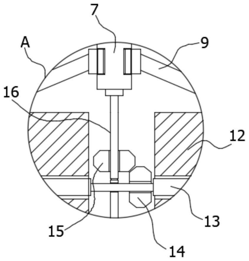
[0018] Refer Figure 1-2 A aeration tank foam treatment device includes a floating ring 1...


PUM


Abstract

The invention discloses a foam treatment device for an aeration tank, which comprises a floating ring, a plastic diaphragm and an annular shell, the floating ring is fixedly connected to the upper end of the plastic diaphragm, the annular shell is fixedly connected to the lower end of the plastic diaphragm, the plastic The two sides of the diaphragm are symmetrically provided with grid sleeves, the two sides of the annular shell are symmetrically opened with openings, and the openings are connected with flow pipes, and the openings communicate with the grid sleeves through the flow pipes. A partition is arranged on the inner wall, and a first rotating shaft is rotatably connected above the partition, and a turbine is fixedly sleeved on the first rotating shaft. The turbine of the present invention rotates to guide the water flow, and a vortex will be formed inside the plastic diaphragm, and the foam around the device will flow to the vortex, and then realize the concentration effect on the foam, and even be guided into the grid sleeve, and the grid sleeve will collect it. Block the foam or sludge, so as to achieve the effect of foam treatment on the surface of sewage.

Description

Technical field [0001] The present invention relates to the field of sewage treatment, and more particularly to a aeration tank foam treatment device. Background technique [0002] The aeration tank utilizes the active sludge method for sewage treatment, providing a certain sewage residence time, satisfying the oxygen content required for good oxygen microorganisms and mixing conditions for the sufficient contact of sewage and active sludge, the aeration tank is mainly by the pool body, aeration The system and the three parts of the inlet and outlet are formed, and the pool is generally built with reinforced concrete, and there is a rectangular shape, square and circular shape. [0003] During the operation, the gas forces the sewage to roll the reaction, the surface of the sewage produces a foam, and the bubble is also doped with sludge, which has the surface of the sewage during the aeration. More foams, the presence of foam hinders the staff to observe the sewage treatment sta...

Claims


Application Information

Patent Timeline
Patent Type & Authority Patents(China)
IPC IPC(8): B01D35/05B01D19/00C02F1/40
CPCB01D35/05B01D19/0031B01D19/0052C02F1/40
Inventor 江超
Owner 浙江润城环保集团股份有限公司
Why Eureka
Try Eureka