Bearing defect detection device and bearing defect detection method

A defect detection and bearing technology, applied in the direction of measuring devices, material analysis through optical means, instruments, etc., can solve the problems that are difficult to meet the process conditions, material performance and production capacity conditions, manual detection speed and accuracy are difficult to quantify, and the surface of the measured workpiece is smooth High-degree requirements and other issues, to achieve the effect of automatic detection, intelligent detection, and compact structure

Active Publication Date: 2020-04-17
宁波三耐机械有限公司
View PDF10 Cites 11 Cited by
  • Summary
  • Abstract
  • Description
  • Claims
  • Application Information

AI Technical Summary

Problems solved by technology

[0004] The speed and accuracy of manual inspection are difficult to quantify due to factors such as individual differences and experience levels. In the qualitative process of surface quality, due to subjective factors of workers, it is easy to cause missed inspections and missed judgments on product surface defects.
Magnetic particle testing, penetrant testing, eddy current testing and other methods are limited in the production site of the bearing industry. For example, magnetic particle testing has high requirements on the surface smoothness of the tested workpiece, and requires technicians with rich experience and mature technology. The requirement for measuring the surface smoothness of the workpiece is high, requiring technicians to have rich experience and mature technology, the detection range is small and the detection speed is slow, and it is difficult to meet the requirements of process conditions, material performance, cost, and production capacity conditions.

Method used


Image

  • Bearing defect detection device and bearing defect detection method
  • Bearing defect detection device and bearing defect detection method
  • Bearing defect detection device and bearing defect detection method

Examples


Embodiment Construction

[0041] The technical solutions of the various embodiments of the present invention will be clearly and completely described below in conjunction with the accompanying drawings. Apparently, the described embodiments are only some of the embodiments of the present invention, not all of them. Based on the embodiments of the present invention, all other embodiments obtained by persons of ordinary skill in the art without making creative efforts fall within the protection scope of the present invention.

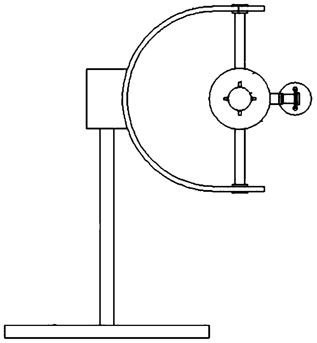
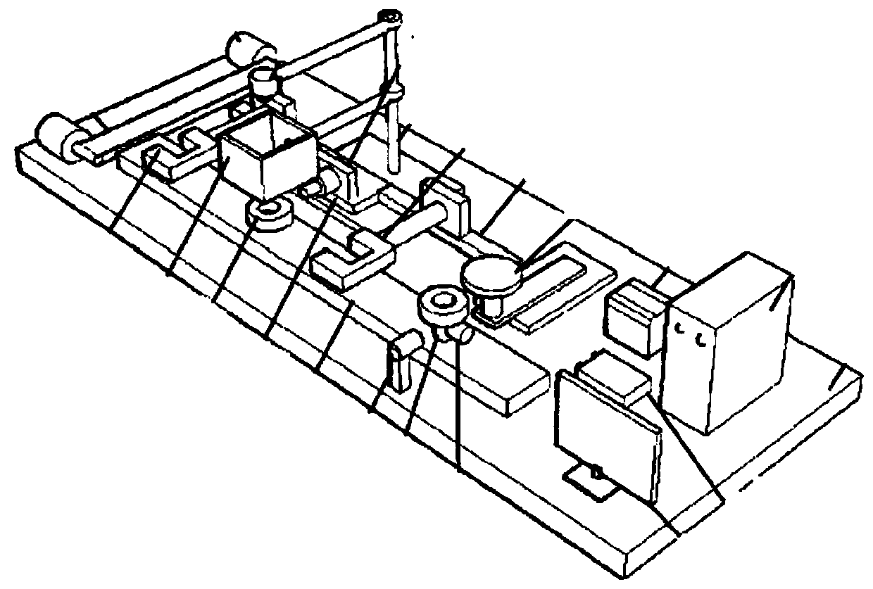
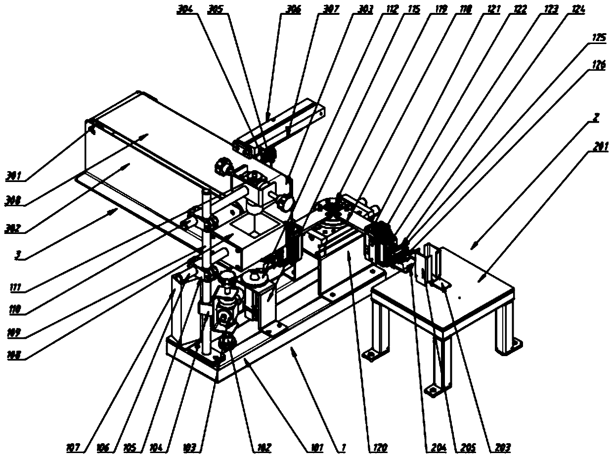
[0042] Figure 3-7 The main technical content of the first specific embodiment is shown. This specific embodiment provides a bearing defect detection device, including a detection part 1, a material loading part 2, a material unloading part 3, a programmable controller 4, and a PC host 5 ; The detection part 1 is located between the loading part 2 and the unloading part 3, and is used to detect bearing defects; the programmable controller 4 and the PC host 5 are located in the con...


PUM


Abstract

The invention discloses a bearing defect detection device and a bearing defect detection method. The bearing defect detection device comprises a detection part, a loading part, an unloading part, a programmable controller and a PC host, wherein a detected bearing is conveyed to a specified position by the loading part, and then grabbed onto a detection position by a clamping jaw of the detection part; a CCD camera carries out picture acquisition, and then the clamping jaw grabs the detected bearing, overturns the detected bearing by 180 degrees, and places the detected bearing on the detectionposition; the CCD camera carries out picture acquisition again, and after the acquisition is completed, the clamping jaw places the detected bearing onto the unloading part; and the PC host processespictures shot by the CCD camera, and judges whether the detected bearing has defects or not. The bearing defect detection device detects the defects of the bearing on the basis of a visual identification system, is high in efficiency, facilitates to realizing automatic detection, and is capable of detecting the upper surface, the lower surface and the outer ring of the bearing at one detection station, and therefore is compact in structure and low in cost.

Description

technical field [0001] The invention relates to a bearing defect detection technology, in particular to a bearing defect detection device and a bearing defect detection method. Background technique [0002] As a common component, bearings are widely used in the industrial field and have different types. The bearing cooperates with the rotation of the mechanical body, which can greatly reduce the resistance during rotation and ensure the accuracy of rotation. Bearing plays an increasingly important role in many industries. It is a component widely used in electromechanical, electrical, petroleum, smelting, and military industries. It can be said that it is needed wherever there is rotation. [0003] Since the processing of bearings includes multiple processes such as forging, rolling, punching, turning, grinding, heat treatment, etc., various defects may appear on the surface of the outer ring of the bearing. Quality defects on the surface of the bearing outer ring seriousl...

Claims


Application Information

Patent Timeline
Patent Type & Authority Applications(China)
IPC IPC(8): B07C5/342G01N21/01G01N21/892
CPCB07C5/3422G01N21/01G01N21/892
Inventor 沈文强
Owner 宁波三耐机械有限公司
Why Eureka
Try Eureka