Electric lifting device for telegraph pole hoop

A technology of electric lifting devices and utility poles, which is applied in transportation and packaging, cranes, etc., can solve problems such as insufficient efficiency, waste of manpower, and unsafety, and achieve the effects of saving time, improving work efficiency, and reducing manpower

Pending Publication Date: 2020-04-17
GUANGDONG POWER GRID CO LTD +1
View PDF0 Cites 0 Cited by
  • Summary
  • Abstract
  • Description
  • Claims
  • Application Information

AI Technical Summary

Problems solved by technology

[0003] In the prior art, the hoop is usually carried by the construction workers to climb to the middle and upper part of the utility pole, and the hoop is manually taken to the designated position and then installed, which is very unsafe; some methods of pushing up the hoop are to be lifted by several people working together to pull the wire at the same time , the efficiency is not enough, and a waste of manpower

Method used


Image

  • Electric lifting device for telegraph pole hoop
  • Electric lifting device for telegraph pole hoop

Examples


Embodiment 1

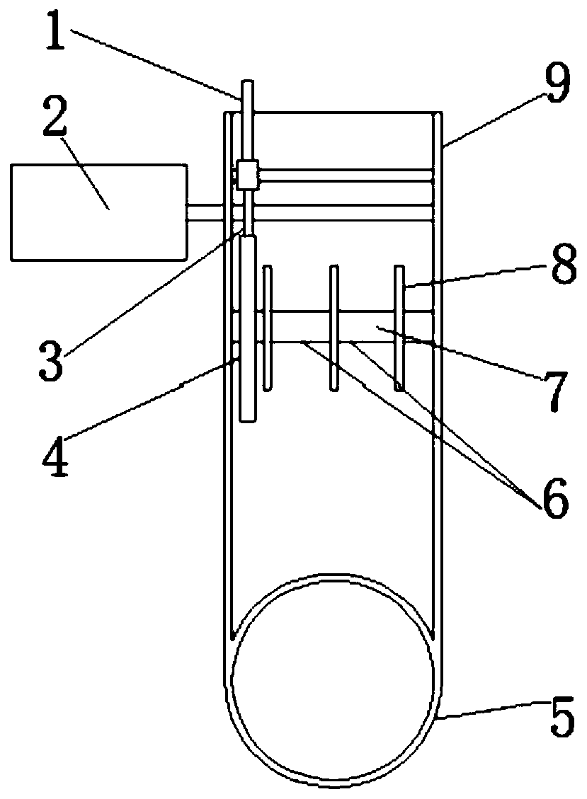
[0022] This embodiment provides an electric hoisting device for utility pole hoops, including a support frame 9, the end of the support frame 9 is fixedly connected with a fixing ring 5, and a motor 2 is installed on the side wall of the support frame 9, and the motor 2 The end of the output shaft of 2 extends into the support frame 9, the outer wall of the output shaft of the motor 2 is fixedly connected with the pinion 3, the inner wall of the support frame 9 is connected with the winding shaft 6, and the outer wall of the winding shaft 6 is fixed A large gear 4 is connected, and the pinion 3 and the large gear 4 mesh with each other. The diameter of the small gear 3 is much smaller than the diameter of the large gear 4. The outer wall of the winding shaft 6 is fixedly connected with a plurality of isolation wire screens 8 A plurality of said isolated wire screens 8 are equidistantly fixedly connected on the outer wall of the winding shaft 7, and a plurality of said isolated ...

Embodiment 2

[0025] The electric hoisting device of the utility pole hoop provided in this embodiment is consistent with the embodiment 1, and only the locking method and the installation surface of the fixing ring are further limited.

[0026] An electric lifting device for a utility pole hoop, comprising a support frame 9, the end of the support frame 9 is fixedly connected with a fixed ring 5, a motor 2 is installed on the side wall of the support frame 9, and the output shaft of the motor 2 The end extends into the support frame 9, the outer wall of the output shaft of the motor 2 is fixedly connected with a pinion 3, the inner wall of the support frame 9 is rotatably connected with a winding shaft 6, and the outer wall of the winding shaft 6 is fixedly connected with a large gear 4. The pinion gear 3 and the bull gear 4 mesh with each other, and the outer wall of the winding shaft 6 is fixedly connected with a plurality of isolation wire screens 8, and the plurality of isolation wire s...


PUM


Abstract

The invention provides an electric lifting device for a telegraph pole hoop. The electric lifting device comprises a supporting frame, a fixing ring is fixedly connected to the tail end of the supporting frame, a motor is installed on a side wall of the supporting frame, the tail end of an output shaft of the motor extends into the supporting frame, a small gear is fixedly connected to the outer wall of the output shaft of the motor, a winding shaft is rotationally connected between the inner walls of the supporting frame, a large gear is fixedly connected to the outer wall of the winding shaft, the small gear is meshed with the large gear, a plurality of isolation line screens are fixedly connected to the outer wall of the winding shaft, the winding shaft is divided into a plurality of winding areas through the isolation line screens, and a self-locking rod matched with the small gear is installed between the inner walls of the supporting frame. According to the electric lifting device for the telegraph pole hoop, the hoop can be lifted by a person electrically instead of by multiple persons together, the working efficiency is improved, manpower is reduced, time is saved, and theelectric lifting device is convenient and rapid to use.

Description

technical field [0001] The invention relates to the field of installation and maintenance of electric power systems, and more specifically, relates to an electric lifting device for hoops of electric poles. Background technique [0002] Telephone pole hoop is a kind of electric power fittings. The commonly used form is a ring-shaped metal component. It is usually installed on the middle and upper part of the telegraph pole after the telegraph pole is erected on the ground and before the wire is pulled. The function of the telegraph pole hoop It is to connect the utility pole and the fixed stay wire, and at the same time distribute the fixed tension to the contact surface between the hoop and the utility pole. To protect the surface of the electric pole at the position of the stay wire from damage, the other end of the fixed stay wire is fixed on the ground. [0003] In the prior art, the hoop is usually carried by the construction workers to climb to the middle and upper pa...

Claims


Application Information

Patent Timeline
Patent Type & Authority Applications(China)
IPC IPC(8): B66C25/00
CPCB66C25/00
Inventor 曾永浩李亮明艾维夏志雄孔令生麦志远彭元泉赵云云李慧珊杨启明
Owner GUANGDONG POWER GRID CO LTD
Why Eureka
Try Eureka