Connecting part reinforcing device in bridge maintenance

A technology for reinforcing devices and connecting parts, applied in bridge maintenance, bridge reinforcement, bridges, etc., can solve problems such as heavy pressure on the repairing device, no overall coherent structure, and cracks, etc., to achieve enhanced tensile and compressive resistance, and connection Enhanced immobilization effect and increased contact area

Active Publication Date: 2020-04-17
上海同固结构工程有限公司
View PDF15 Cites 2 Cited by
  • Summary
  • Abstract
  • Description
  • Claims
  • Application Information

AI Technical Summary

Problems solved by technology

[0002] During the long-term use of bridges and roads, cracks will appear on bridges and roads due to their own load-bearing and vibration generated by vehicles. The traditional repair method is usually to break and open grooves at the cracks and then refill them. The reinforcement effect and connection effect are low, and cracks are easy to occur again. There are also some repair methods that pre-embed connecting steel bars on both sides of the cracks, but the connection effect between the steel bars and the concrete layer is poor. The above repair methods can be used in long-term outdoor environments Especially in working conditions with large temperature differences and irregular crack shapes, stress concentration areas are prone to occur, and existing repair devices such as CN208250933U and CN207295506U all use support expansion structures that can be screwed on both sides, but they are all single and independent The external pressure is independently decomposed, and there is no overall coherent structure, so the tensile and compressive resistance after the overall repair is insufficient, and when repairing cracks with different depths and different lengths, the external pressure or tension acts on different positions. When the repair device is subjected to different forces, it may cause local overpressure of the repair device and damage

Method used


Image

  • Connecting part reinforcing device in bridge maintenance
  • Connecting part reinforcing device in bridge maintenance
  • Connecting part reinforcing device in bridge maintenance

Examples


Embodiment Construction

[0020] The following will clearly and completely describe the technical solutions in the embodiments of the present invention with reference to the accompanying drawings in the embodiments of the present invention. Obviously, the described embodiments are only some, not all, embodiments of the present invention. Based on the embodiments of the present invention, all other embodiments obtained by persons of ordinary skill in the art without making creative efforts belong to the protection scope of the present invention.

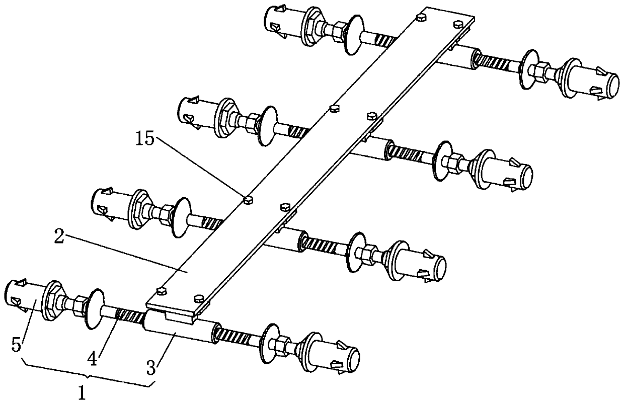
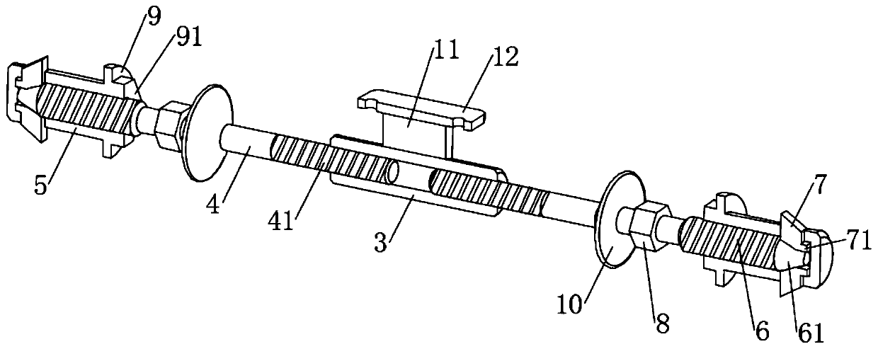
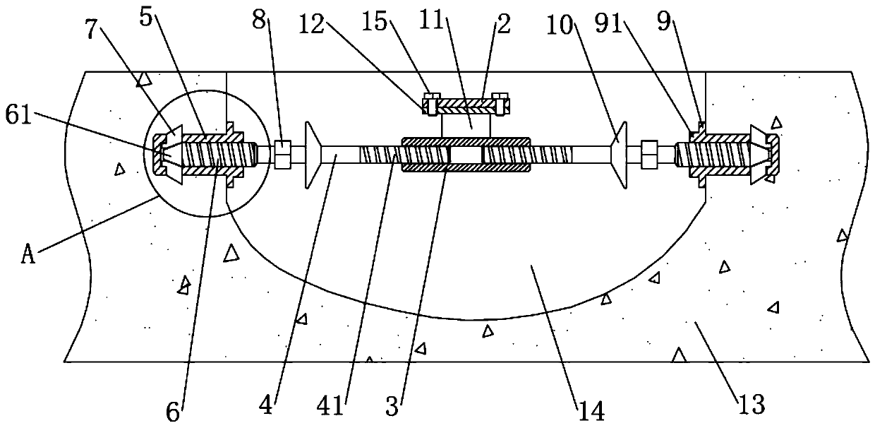
[0021] The present invention provides such Figure 1-4 The shown connecting part reinforcement device in bridge maintenance includes bridge pavement 13, multiple sets of connecting rod assemblies 1 arranged in parallel, and beam plates 2 connecting and fixing multiple sets of connecting rod assemblies 1, the bridge pavement 13 Slots are opened at the cracks, and multiple sets of connecting rod assemblies 1 and beam plates 2 for connecting and fixing multiple s...


PUM


Abstract

The invention discloses a connecting part reinforcing device in bridge maintenance and relates to the field of bridge maintenance. The connecting part reinforcing device comprises a bridge pavement, multiple sets of connecting rod assemblies arranged in parallel and a cross beam plate for connecting and fixing the multiple sets of connecting rod assemblies, the multiple sets of connecting rod assemblies and the cross beam plate are arranged in an open groove in the crack of the bridge pavement, and each connecting rod assembly comprises a sleeve, a connecting rod and a plug. According to the invention, the plug connecting end arranged at the end part of the connecting rod is in threaded connection with the plug; when the plug connecting end is ejected into the plug, a conical ejector headmakes contact with the inner end of a claw nail, the triangular nail-shaped part of the claw nail is ejected outwards, the outer end of the claw nail is ejected out and pierces into the inner wall ofthe connecting hole groove at the moment, the plug is effectively prevented from falling out of the connecting hole groove, and compared with a traditional expansion bolt connecting mode, the connecting and fixing effect is greatly enhanced.

Description

technical field [0001] The invention relates to the field of bridge maintenance, in particular to a connecting portion reinforcing device in bridge maintenance. Background technique [0002] During the long-term use of bridges and roads, cracks will appear on bridges and roads due to their own load-bearing and vibration generated by vehicles. The traditional repair method is usually to break and open grooves at the cracks and then refill them. The reinforcement effect and connection effect are low, and cracks are easy to occur again. There are also some repair methods that pre-embed connecting steel bars on both sides of the cracks, but the connection effect between the steel bars and the concrete layer is poor. The above repair methods can be used in long-term outdoor environments Especially in working conditions with large temperature differences and irregular crack shapes, stress concentration areas are prone to occur, and existing repair devices such as CN208250933U and ...

Claims


Application Information

Patent Timeline
IPC IPC(8): E01D22/00
CPCE01D22/00
Inventor 付君义王扬王烁史育晓方碧子王秀成张振华姜波徐国庆翟文武李立书刘保庆郭宇飞王世超孙娇娇孙立娜徐冰王祎楠李小可刘海波
Owner 上海同固结构工程有限公司
Why Eureka
Try Eureka