
Fully-embedded steel beam combined floor slab and construction method thereof

A technology for combining floor slabs and construction methods, which is applied in the directions of slabs, buildings, building components, etc., can solve the problems of large thickness of composite slabs, weak connection between concrete and steel bars, etc., achieves low self-weight of slabs, eliminates hidden dangers of welding quality, and improves stress. performance effect

Pending Publication Date: 2020-04-17
SHANGHAI CONSTR NO 5 GRP CO LTD
View PDF0 Cites 3 Cited by
  • Summary
  • Abstract
  • Description
  • Claims
  • Application Information

AI Technical Summary

Problems solved by technology

[0006] The purpose of the present invention is to provide a fully embedded steel beam composite floor and its construction method to solve the problems of the existing composite floor with excessive thickness and weak connection between concrete and steel bars

Method used


Image

  • Fully-embedded steel beam combined floor slab and construction method thereof
  • Fully-embedded steel beam combined floor slab and construction method thereof
  • Fully-embedded steel beam combined floor slab and construction method thereof

Examples


Embodiment 1

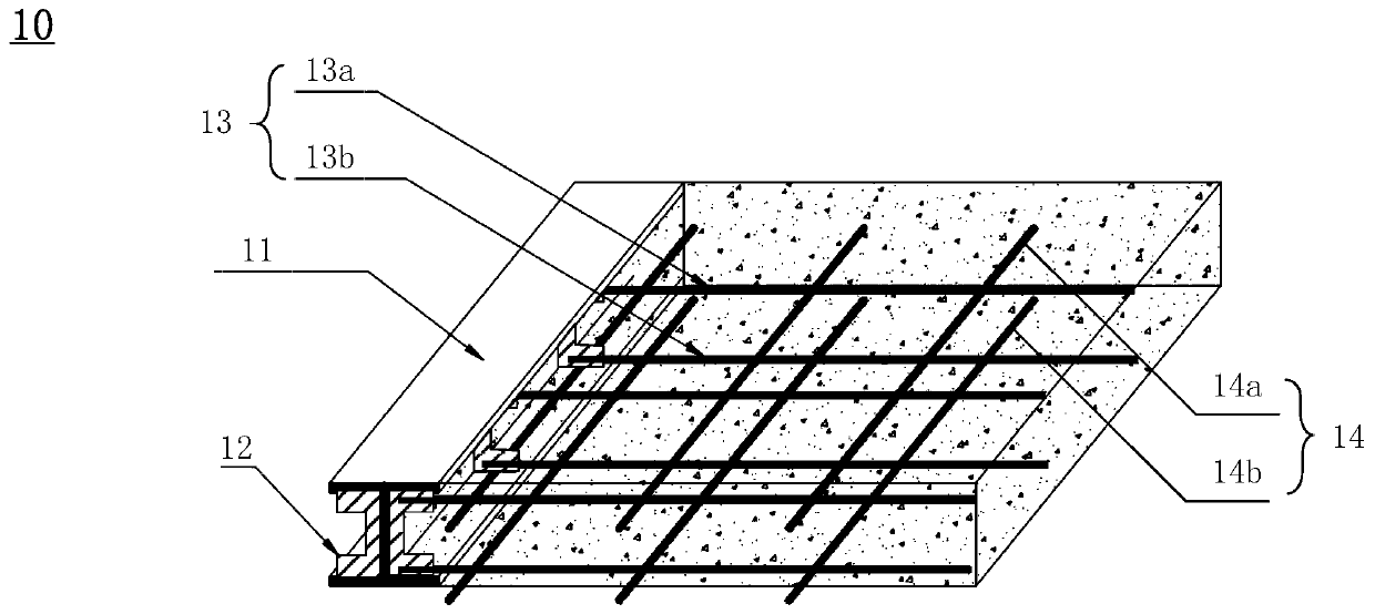
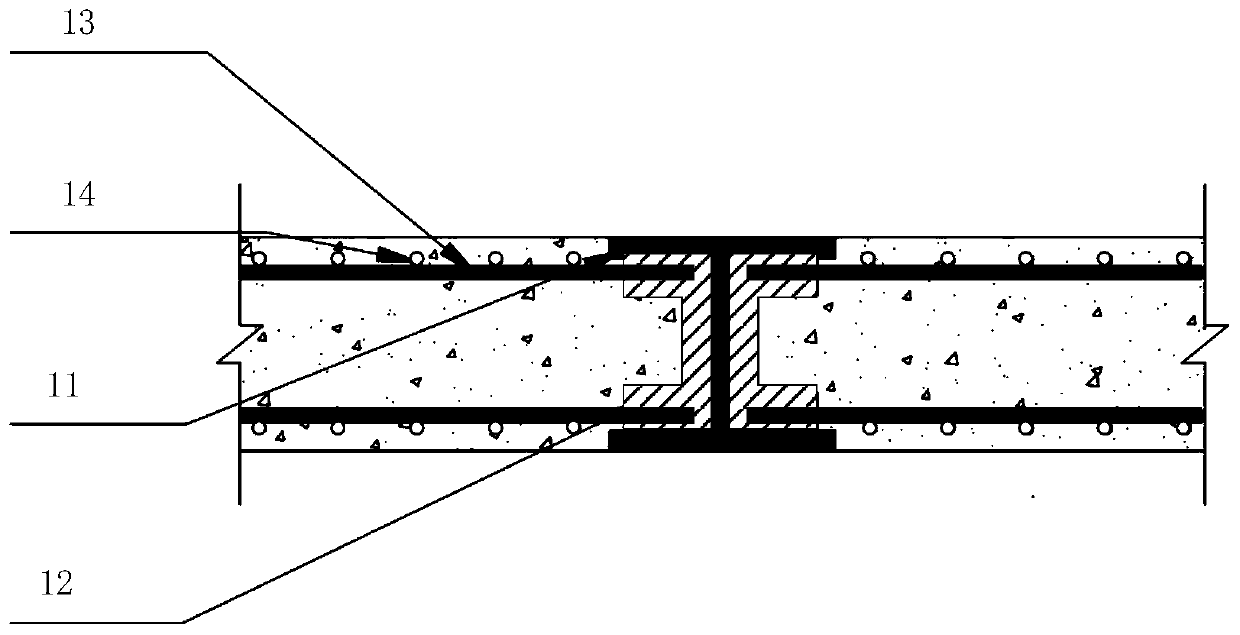
[0042] Please refer to figure 1 and figure 2 , which is a schematic structural diagram of a fully embedded steel beam composite floor slab according to Embodiment 1 of the present invention. Such as figure 1 and figure 2 As shown, the fully embedded steel beam composite floor 10 includes: floor steel beams 11, C-shaped stiffeners 12, stressed steel bars 13, distributed steel bars 14 and concrete layers 15; the floor steel beams 11 have at least one C-shaped groove, the C-shaped groove extends along the length direction of the floor steel beam 11; the stressed steel bar 13 is fixedly connected with the C-shaped stiffener 12, and the C-shaped stiffener 12 is The floor steel beams 11 are arranged in the C-shaped groove at intervals in the length direction, and are fixedly connected with the C-shaped groove; the stressed steel bars 13 are arranged crosswise with the distributed steel bars 14, and the concrete layer 15 is poured On the stressed steel bar 13 and the distribute...

Embodiment 2

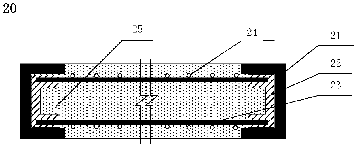
[0068] Please refer to image 3 , which is a side view of a fully embedded steel beam composite floor slab according to Embodiment 2 of the present invention. Such as image 3 As shown, the fully embedded steel beam composite floor 20 includes: floor steel beams 21, C-shaped stiffeners 22, stressed steel bars 23, distributed steel bars 24 and concrete layers 25; the floor steel beams 21 have at least one C-shaped groove, the C-shaped groove extends along the length direction of the floor steel beam 21; the stressed steel bar 23 is fixedly connected with the C-shaped stiffener 22, and the C-shaped stiffener 22 is The floor steel beams 21 are arranged in the C-shaped groove at intervals in the length direction, and are fixedly connected with the C-shaped groove; the stressed steel bars 23 are arranged crosswise with the distributed steel bars 24, and the concrete layer 25 is poured On the stressed steel bar 23 and the distributed steel bar 24.

[0069] Specifically, the floor...


PUM


Abstract

The invention provides a fully-embedded steel beam combined floor slab and a construction method thereof. The fully-embedded steel beam combined floor slab comprises a floor slab steel beam, C-shapedstiffening ribs, stressed steel bars, distributing bars and a concrete layer, wherein the floor slab steel beam comprises at least one C-shaped groove which extends in the length direction of the floor slab steel beam; the stressed steel bars are fixedly connected to the C-shaped stiffening ribs; the C-shaped stiffening ribs are arranged in the C-shaped groove at intervals in the length directionof the floor slab steel beam and are fixedly connected to the C-shaped groove; the stressed steel bars and the distributing bars are crosswise arranged; and the concrete layer is poured on the stressed steel bars and the distributing bars. In the fully-embedded steel beam combined floor slab and the construction method thereof, the overall cast-in-place of concrete is realized by adopting the floor slab steel beam with the C-shaped groove in conjunction with the connection of the C-shaped stiffening ribs and the steel bars, so that the floor slab steel beam is embedded in the concrete layer, and thereout, the thickness of the combined floor slab is reduced; and the concrete is firmly connected to the steel bars, and thus, the combined floor slab has relatively good quality.

Description

technical field [0001] The invention relates to the technical field of building construction, in particular to a fully embedded steel beam composite floor slab and a construction method thereof. Background technique [0002] In my country's industrial and civil buildings, reinforced concrete structures are widely used because of their wide range of raw materials, mature technology and low cost. However, with the improvement of building height and seismic requirements, as well as the increasing requirements of modern buildings for storey height, large span and large space, the application of reinforced concrete structures has been more restricted. [0003] Steel structure buildings use steel plates or section steel instead of reinforced concrete, which has higher strength and better earthquake resistance, and because the components can be manufactured in a factory and installed on site, the construction period is greatly reduced. In addition, steel can be reused, which can g...

Claims


Application Information

Patent Timeline
Patent Type & Authority Applications(China)
IPC IPC(8): E04B5/32
CPCE04B5/32E04B2005/324
Inventor 徐大为潘峰杨子明王晓旻黄泽志
Owner SHANGHAI CONSTR NO 5 GRP CO LTD
Learn More