
Novel locking device

A locking device, a new type of technology, applied in vehicle locks, electric locks, building locks, etc., can solve the problems of affecting the appearance, poor dimensional stability of parts, enlargement, etc., and achieve the effect of improving product effect, optimizing structure, and reducing production cost

Pending Publication Date: 2020-04-17
宁波岚骐智能科技有限公司
View PDF1 Cites 0 Cited by
  • Summary
  • Abstract
  • Description
  • Claims
  • Application Information

AI Technical Summary

Problems solved by technology

However, the existing refueling wicket generally uses a lever to control the opening and closing of the lock pin. The lever enlarges the dimensional tolerance of the part, resulting in poor dimensional stability of the part. The position of the screw shaft is controlled by the stroke control chute, but it must be fixed by the lever. The point corresponds to the screw shaft, which is represented by a point at the height of the screw shaft. The height of the screw shaft is unstable, which means that the panel height of the refueling door is unstable, and there is a large surface difference between the body and the appearance.

Method used


Image

  • Novel locking device
  • Novel locking device
  • Novel locking device

Examples


Embodiment

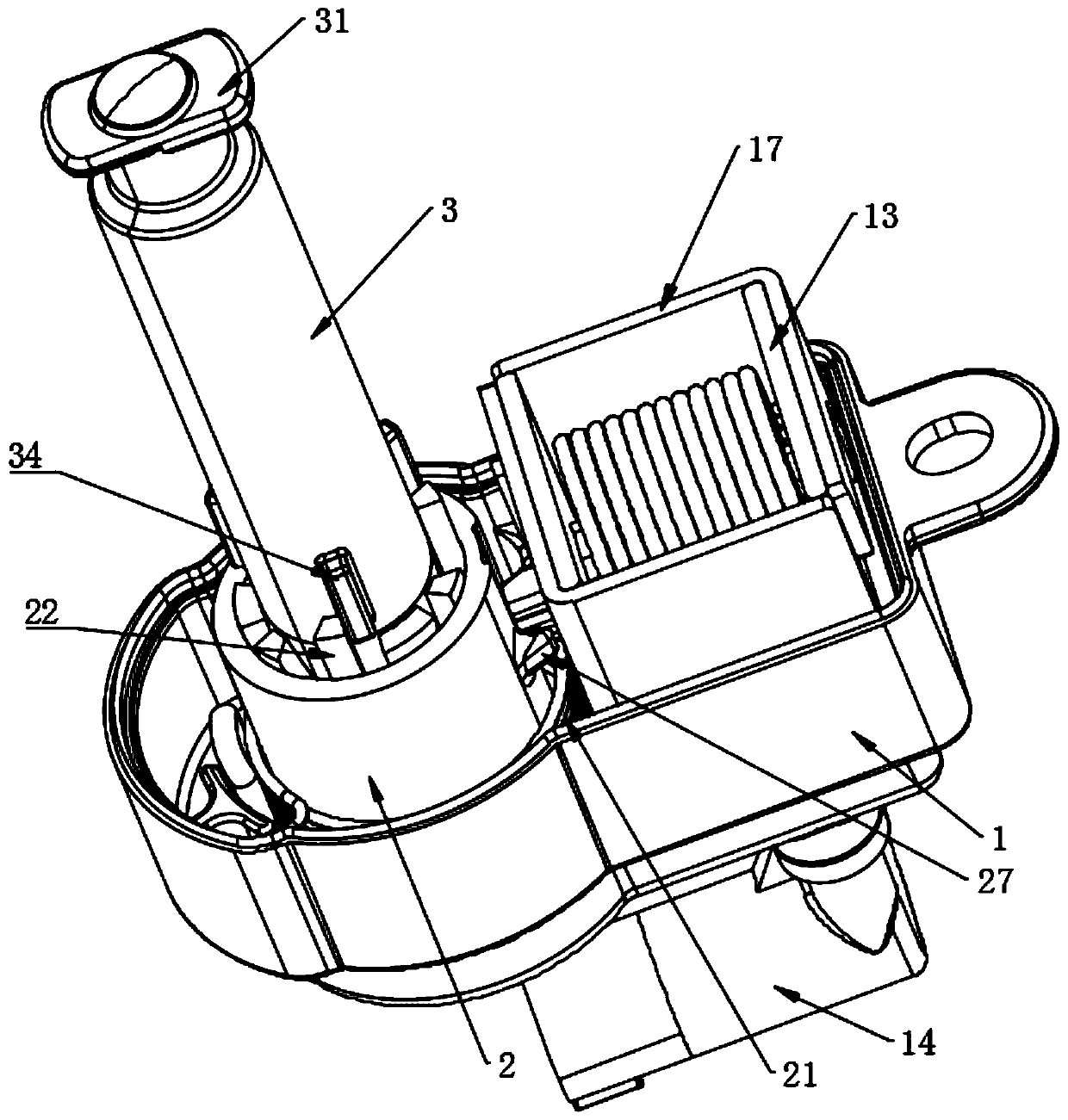
[0033] Embodiment: a kind of novel locking device, as figure 1 As shown, it includes the lower casing 1, the lower casing 1 is provided with a self-rotating stop block 2, the middle of the stop block 2 is inserted with the actuator rod 3, and the top of the actuator rod 3 is provided with a lock pin 31 that cooperates with the refueling door. When the actuator rod 3 is inserted into the stop block 2, it will drive the stop block 2 to rotate.

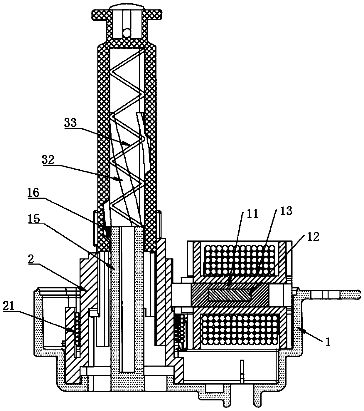
[0034] Such as figure 1 with figure 2 As shown, the lower casing 1 is provided with a winding bracket 13 and a slider 11 located outside the stop block 2, a through hole is opened in the middle of the winding bracket 13 for the slider 11 to fit through, and the winding bracket 13 is wound outside There is a coil, the slider 11 is embedded with a permanent magnet 12, the stop block 2 is provided with a groove for the end of the slider 11 to snap into, and the lower casing 1 is provided with a power connector 14 electrically connected t...


PUM


Abstract

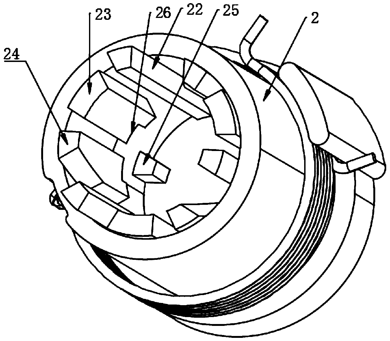
The invention discloses a novel locking device. The novel locking device comprises a lower shell, a stop block capable of rotating is arranged in the lower shell, an execution rod is inserted in the middle of the stop block, a lock pin matched with a small refueling door is arranged at the top end of the execution rod, when the execution rod is inserted into the stop block, the stop block is driven to rotate, the stop block is sleeved with a torsional spring, one end of the torsional spring is fixed to the lower shell, the other end of the torsional spring is fixed to the stop block, a guide rod inserted into the execution rod in an attached mode is arranged in the lower shell, a first protrusion is arranged at the top end of the guide rod, a spiral groove allowing the first protrusion toslide in an attached mode is formed in the inner wall of the execution rod, a compression spring abutting against the guide rod is arranged in the execution rod, a second protrusion is arranged at theend, inserted into the stop block, of the execution rod, a first protruding block, a second protruding block and a third protruding block are sequentially arranged on the inner wall of the stop blockside by side, and the first protruding block is in a long strip shape with the length larger than that of the second protruding block. The novel locking device has beautiful appearance.

Description

technical field [0001] The present invention relates to a kind of controller of fuel oil door of automobile, more specifically, it relates to a kind of novel locking device. Background technique [0002] The locking device is installed on the inner side of the small refueling door of the car, and has the functions of locking / unlocking the small refueling door and popping open / folding the small refueling door. [0003] The patent with publication number CN208180769U and announcement date 20181204 discloses a refueling wicket with a sealing ring, including a fuel wicket body, the refueling wicket body is rectangular, and the middle part of the fuel wicket body is concavely provided with a Cover, the middle part of the square cover is provided with a circular refueling hole, the surrounding of the refueling hole is provided with a sealing ring, the small refueling door body on the right side of the square cover is rotated and provided with a small dustproof door, the The perip...

Claims


Application Information

Patent Timeline
Patent Type & Authority Applications(China)
IPC IPC(8): E05B83/28E05B81/04
CPCE05B83/28E05B81/04
Inventor 曹苗丹冯保华
Owner 宁波岚骐智能科技有限公司
Learn More