Cloud particle collector

A collector and particle technology, applied in the field of collectors, can solve the problems of large particle collection distortion and inapplicable particle collection

Pending Publication Date: 2020-04-17
FOSHAN NANHAI KERI ELECTRONICS
View PDF1 Cites 3 Cited by
  • Summary
  • Abstract
  • Description
  • Claims
  • Application Information

AI Technical Summary

Problems solved by technology

However, after many sampling tests, it was found that the particle collection using this particle collector in the duct

Method used


Image

  • Cloud particle collector
  • Cloud particle collector
  • Cloud particle collector

Examples


Embodiment Construction

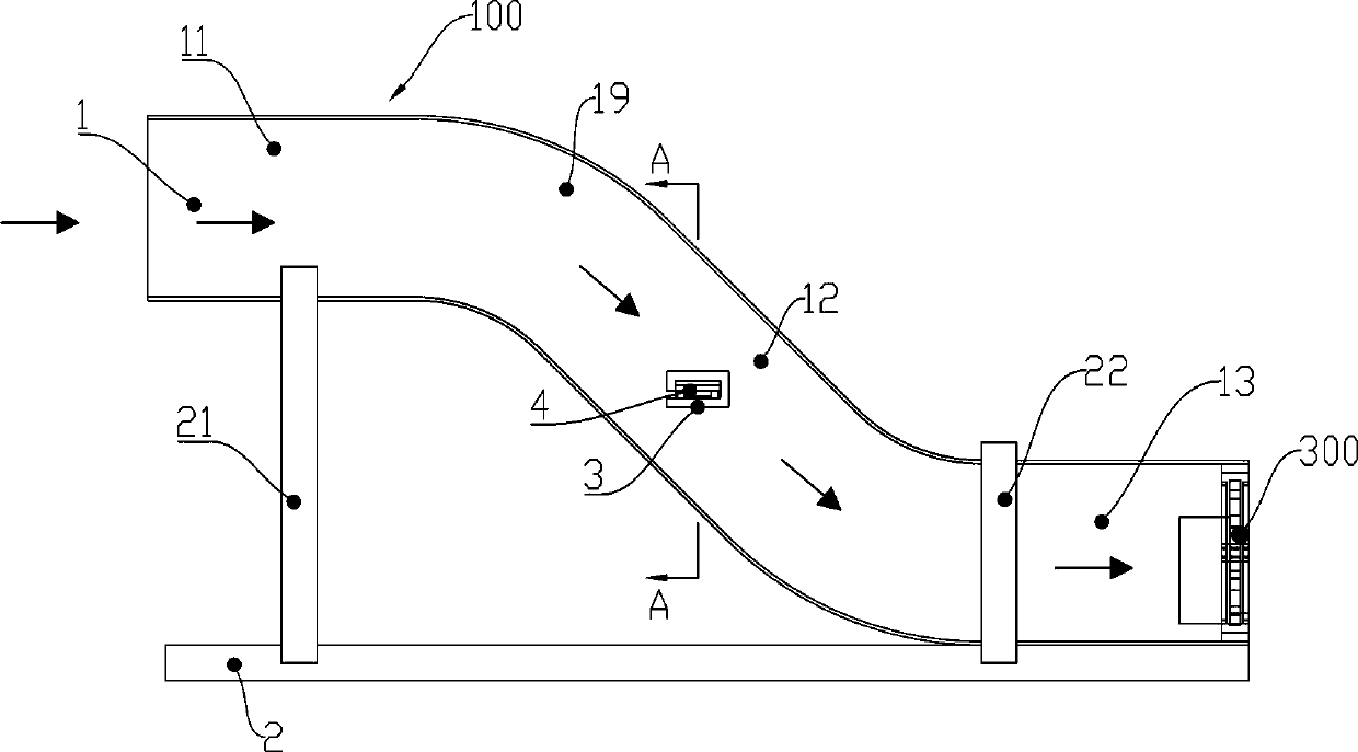
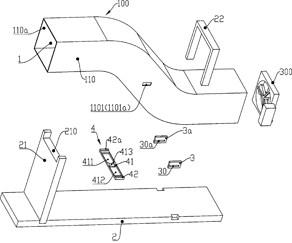
[0024] Such as figure 1 , figure 2 and image 3As shown, the present invention proposes a cloud particle collector, including a housing 100, the housing 100 is provided with an airflow passage 1; The oblique passage 12 at the end and arranged obliquely, the air inlet passage 11 is arranged in a horizontal direction, and the oblique passage 12 forms an angle of 45° with the horizontal plane; The support frame 4, the support frame 4 is positioned on the housing 100 and can allow the airflow in the inclined channel 12 to pass through, and the sampling sheet is arranged horizontally on the support frame 4 when sampling is in operation so as to be able to collect the cloud and mist particles contained in the flowing airflow in the inclined channel 12; an axial fan 300 is also included, and the axial fan 300 is installed on the housing 100 and is located downstream of the support frame 4 Therefore, the airflow in the airflow channel 1 can be allowed to flow when it works. When ...


PUM


Abstract

A cloud particle collector comprises a shell, and an airflow channel is formed in the shell. The collector is characterized in that the airflow channel comprises an air inlet channel and an inclined channel communicated with the tail end of the air inlet channel and arranged obliquely, the air inlet channel is arranged in the horizontal direction, and a 45-degree included angle is formed between the inclined channel and the horizontal plane. The beneficial effects of the invention are that as the air inlet channel is arranged in the horizontal direction, therefore, airflow cannot form a largeamount of turbulent flow, particles in the airflow cannot collide with one another under the action of the turbulent flow to be agglomerated or split, the size of the particles cannot be increased ordecreased, and the distribution density of the particles, located outside the airflow channel and entering the airflow channel, in the airflow cannot be obviously changed. Therefore, the distributiondensity and the volume of the particles outside the airflow channel are basically consistent with those of the particles in the airflow entering the airflow channel.

Description

[0001] The invention relates to a collector capable of collecting cloud and mist particles, in particular to a cloud and mist particle collector with a flow channel. [0002] technical background [0003] In the field of coal mining, since most of the ore seams are far away from the surface, it is not possible to use open-pit mining, but must use underground mining. When mining underground coal mines, diggers need to go deep into the ground, forming a tunnel for mining coal mines under the surface. The ventilation effect of the tunnel is generally poor. If the dust accumulates to a certain concentration, it may cause an explosion due to sparks, and inhaling too much dust will also cause miners to suffer from chronic lung diseases such as pneumoconiosis, resulting in reduced life expectancy. In order to be able to effectively monitor the concentration and volume of particles floating in the air in the duct, the first task is to collect the particles. The particle collector has ...

Claims


Application Information

Patent Timeline
IPC IPC(8): G01N15/00G01N15/06G01N1/22G01N1/24
CPCG01N1/2226G01N1/24G01N15/00G01N15/06G01N2001/245G01N2015/0096
Inventor 卢薇徐锐祝文军梁羽翔
Owner FOSHAN NANHAI KERI ELECTRONICS
Why Eureka
Try Eureka